How to Use led driver arus constant: Examples, Pinouts, and Specs
Introduction
A constant current LED driver is an electronic component designed to regulate the current flowing through LED lights. Unlike constant voltage drivers, this component ensures a steady current supply, which is critical for maintaining consistent brightness and protecting LEDs from overcurrent damage.
Explore Projects Built with led driver arus constant
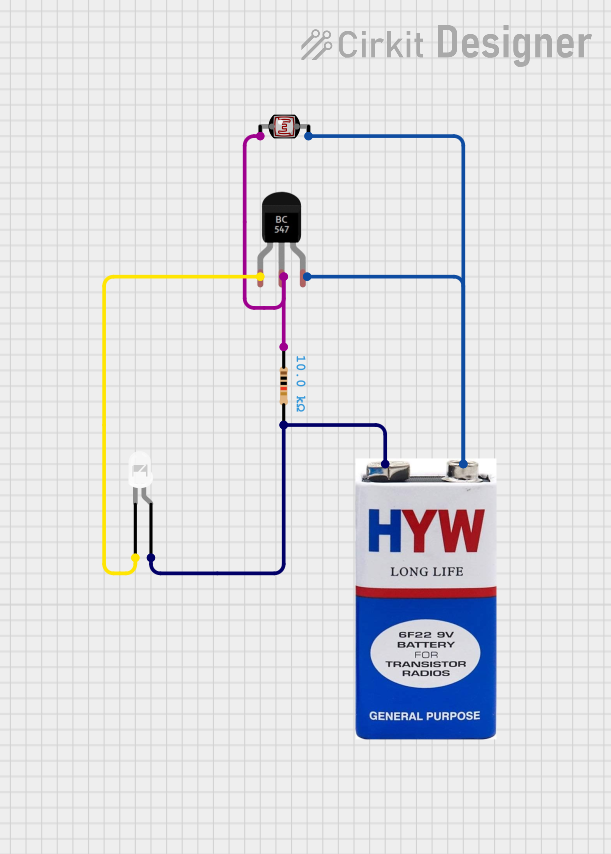
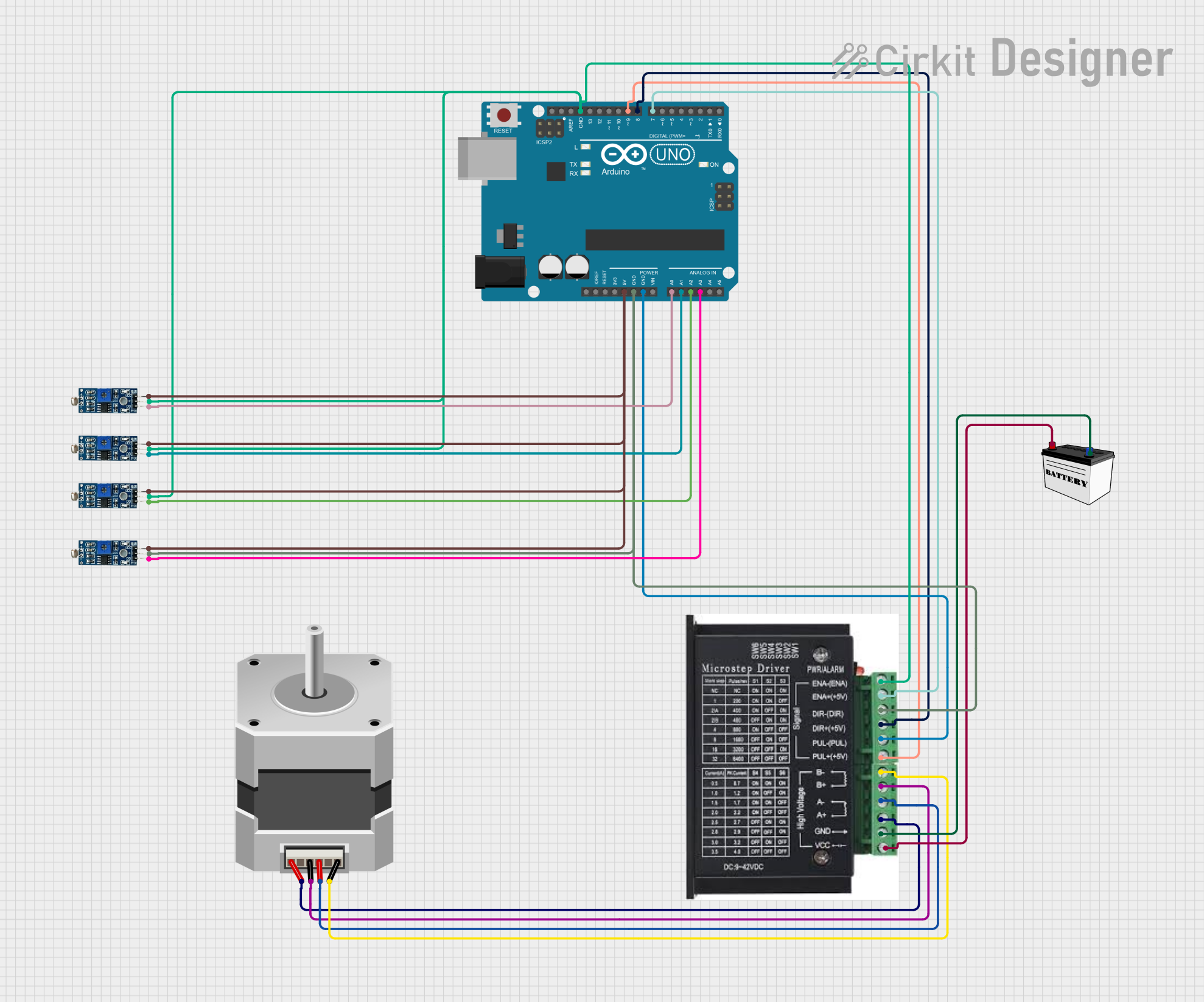
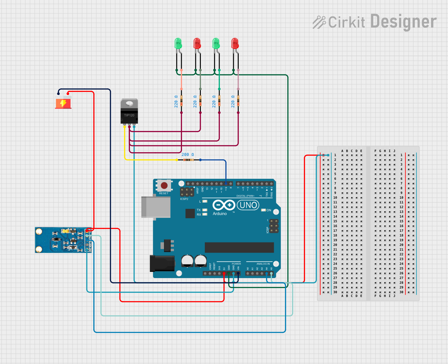
Explore Projects Built with led driver arus constant
Common Applications and Use Cases
- LED lighting systems in residential, commercial, and industrial environments
- Backlighting for displays and signage
- Automotive LED lighting
- Architectural lighting installations
- LED strips and arrays requiring uniform brightness
Technical Specifications
Below are the general technical specifications for a constant current LED driver. Specific values may vary depending on the model and manufacturer.
| Parameter | Specification |
|---|---|
| Input Voltage Range | 12V to 48V DC (varies by model) |
| Output Current Range | 350mA, 700mA, or 1A (constant current) |
| Output Voltage Range | 3V to 36V (depending on LED configuration) |
| Efficiency | Up to 90% |
| Dimming Support | PWM, 0-10V, or TRIAC (model-dependent) |
| Protection Features | Overcurrent, overvoltage, short circuit |
| Operating Temperature | -20°C to +70°C |
| Form Factor | Compact, PCB-mounted or enclosed module |
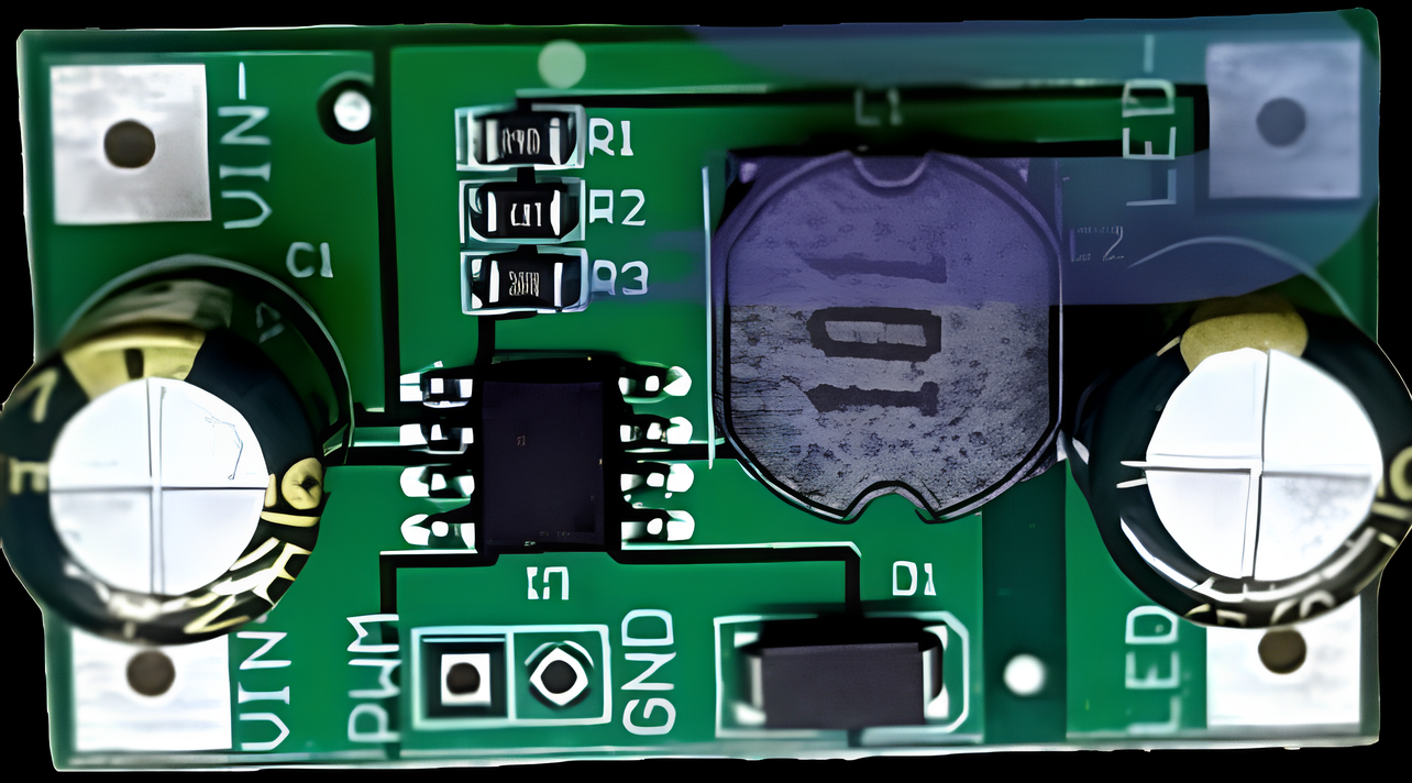
Pin Configuration and Descriptions
The pin configuration for a typical constant current LED driver is as follows:
| Pin Name | Description |
|---|---|
| VIN+ | Positive input voltage terminal |
| VIN- | Negative input voltage terminal (ground) |
| LED+ | Positive output terminal for LED connection |
| LED- | Negative output terminal for LED connection |
| DIM | Dimming control input (PWM or analog signal) |
Usage Instructions
How to Use the Component in a Circuit
- Power Supply Selection: Ensure the input voltage matches the driver's specified range. For example, if the driver accepts 12V-48V DC, use a power supply within this range.
- Connect the Input: Attach the positive terminal of the power supply to the
VIN+pin and the negative terminal to theVIN-pin. - Connect the LED: Connect the positive terminal of the LED (or LED array) to the
LED+pin and the negative terminal to theLED-pin. - Dimming Control (Optional): If dimming is required, connect a PWM or analog signal to the
DIMpin. Refer to the driver’s datasheet for the supported dimming method and signal range. - Power On: Turn on the power supply. The driver will regulate the current to the LED, ensuring consistent brightness.
Important Considerations and Best Practices
- Match the Driver to the LED: Ensure the driver's output current matches the LED's rated current. For example, if the LED is rated for 700mA, use a driver with a 700mA constant current output.
- Thermal Management: LEDs and drivers can generate heat during operation. Use proper heat sinks or ventilation to prevent overheating.
- Dimming Compatibility: Verify that the dimming method (e.g., PWM, 0-10V) is compatible with your LED driver and control system.
- Polarity: Always connect the input and output terminals with the correct polarity to avoid damage to the driver or LEDs.
Example: Using a Constant Current LED Driver with Arduino UNO
Below is an example of controlling the dimming function of a constant current LED driver using an Arduino UNO and PWM.
// Example: Dimming an LED using Arduino UNO and a constant current LED driver
// Connect the DIM pin of the LED driver to Arduino pin 9

const int dimPin = 9; // PWM pin connected to the DIM input of the LED driver
int brightness = 0;   // Initial brightness level (0-255)
int fadeAmount = 5;   // Amount to change brightness by each step

void setup() {
  pinMode(dimPin, OUTPUT); // Set the DIM pin as an output
}

void loop() {
  analogWrite(dimPin, brightness); // Send PWM signal to control brightness

  // Adjust brightness for a fade effect
  brightness = brightness + fadeAmount;

  // Reverse direction of fade at the ends of the range
  if (brightness <= 0 || brightness >= 255) {
    fadeAmount = -fadeAmount;
  }

  delay(30); // Delay to control fade speed
}
Troubleshooting and FAQs
Common Issues and Solutions
| Issue | Possible Cause | Solution |
|---|---|---|
| LED does not light up | Incorrect wiring or polarity | Double-check all connections and polarity. |
| LED flickers | Incompatible dimming signal or noisy input | Use a compatible dimming signal; filter the input. |
| Driver overheats | Insufficient ventilation or overloading | Improve cooling or ensure the load matches specs. |
| LED brightness is inconsistent | Driver output current mismatch | Use a driver with the correct constant current. |
FAQs
Can I use a constant current LED driver with multiple LEDs? Yes, but ensure the LEDs are connected in series, and the total forward voltage is within the driver's output voltage range.
What happens if I exceed the driver's input voltage range? Exceeding the input voltage range can damage the driver. Always use a power supply within the specified range.
Can I use a constant current LED driver for non-LED applications? No, these drivers are specifically designed for LEDs and may not work properly with other loads.
How do I know if my LED driver supports dimming? Check the datasheet or product label for dimming specifications (e.g., PWM, 0-10V).
By following this documentation, you can effectively use a constant current LED driver to power and control your LED lighting systems.