Cirkit Designer Logo
Cirkit Designer
Your all-in-one circuit design IDE
Home / 
Component Documentation

How to Use 3 way Switch: Examples, Pinouts, and Specs

Image of 3 way Switch
Cirkit Designer LogoDesign with 3 way Switch in Cirkit Designer

Introduction

A 3-way switch is an electronic component that enables control of a light fixture or other electrical load from two different locations. This type of switch is commonly used in residential and commercial settings, particularly in areas such as staircases, hallways, and large rooms where multi-point control is convenient for users. The 3-way switch is an essential component in modern electrical installations, providing both functionality and flexibility.

Explore Projects Built with 3 way Switch

Use Cirkit Designer to design, explore, and prototype these projects online. Some projects support real-time simulation. Click "Open Project" to start designing instantly!
Toggle Switch Controlled Lamp Circuit with Banana Sockets
Image of STAIRCASE: A project utilizing 3 way Switch in a practical application
This circuit consists of two toggle switches and a red lamp connected to panel mount banana sockets. The switches control the connection between the red and black banana sockets, allowing the lamp to be turned on or off depending on the switch positions.
Cirkit Designer LogoOpen Project in Cirkit Designer
Battery-Powered LED Array with Rocker Switch Control
Image of Natt. fr. verkefni: A project utilizing 3 way Switch in a practical application
This circuit consists of a 3.3V battery powering four red LEDs connected in parallel, with a rocker switch controlling the connection to ground. When the switch is closed, all LEDs will light up simultaneously.
Cirkit Designer LogoOpen Project in Cirkit Designer
Battery-Powered LED Indicator Circuit with Rocker Switches
Image of Intern 1: A project utilizing 3 way Switch in a practical application
This circuit consists of three LEDs (red, green, and yellow) each connected in series with a 1k Ohm resistor and controlled by individual rocker switches. The LEDs share a common ground with a 9V battery, and the switches are connected to the positive terminal of the battery, allowing each LED to be turned on or off independently.
Cirkit Designer LogoOpen Project in Cirkit Designer
Logic Gate Experimentation Board with DIP Switch Control and LED Indicators
Image of Lab 4 Encoder: A project utilizing 3 way Switch in a practical application
This circuit is a digital logic demonstration setup using a 3-position DIP switch to control the logic states of a series of gates (inverters, AND, and OR) from the 74HC logic family. The output of these gates is used to drive three LEDs through current-limiting resistors, indicating the logic levels after processing by the gates. The circuit is powered by a DC power source, with all ICs sharing a common ground and VCC.
Cirkit Designer LogoOpen Project in Cirkit Designer

Explore Projects Built with 3 way Switch

Use Cirkit Designer to design, explore, and prototype these projects online. Some projects support real-time simulation. Click "Open Project" to start designing instantly!
Image of STAIRCASE: A project utilizing 3 way Switch in a practical application
Toggle Switch Controlled Lamp Circuit with Banana Sockets
This circuit consists of two toggle switches and a red lamp connected to panel mount banana sockets. The switches control the connection between the red and black banana sockets, allowing the lamp to be turned on or off depending on the switch positions.
Cirkit Designer LogoOpen Project in Cirkit Designer
Image of Natt. fr. verkefni: A project utilizing 3 way Switch in a practical application
Battery-Powered LED Array with Rocker Switch Control
This circuit consists of a 3.3V battery powering four red LEDs connected in parallel, with a rocker switch controlling the connection to ground. When the switch is closed, all LEDs will light up simultaneously.
Cirkit Designer LogoOpen Project in Cirkit Designer
Image of Intern 1: A project utilizing 3 way Switch in a practical application
Battery-Powered LED Indicator Circuit with Rocker Switches
This circuit consists of three LEDs (red, green, and yellow) each connected in series with a 1k Ohm resistor and controlled by individual rocker switches. The LEDs share a common ground with a 9V battery, and the switches are connected to the positive terminal of the battery, allowing each LED to be turned on or off independently.
Cirkit Designer LogoOpen Project in Cirkit Designer
Image of Lab 4 Encoder: A project utilizing 3 way Switch in a practical application
Logic Gate Experimentation Board with DIP Switch Control and LED Indicators
This circuit is a digital logic demonstration setup using a 3-position DIP switch to control the logic states of a series of gates (inverters, AND, and OR) from the 74HC logic family. The output of these gates is used to drive three LEDs through current-limiting resistors, indicating the logic levels after processing by the gates. The circuit is powered by a DC power source, with all ICs sharing a common ground and VCC.
Cirkit Designer LogoOpen Project in Cirkit Designer

Technical Specifications

General Characteristics

  • Manufacturer: Nam
  • Part ID: 3 way
  • Type: Mechanical Switch
  • Ratings:
    • Voltage: Typically rated for 120VAC or 240VAC (depending on the region)
    • Current: Commonly rated for 15A or 20A
  • Terminal Type: Screw terminals or push-in terminals
  • Switch Configuration: SPDT (Single Pole, Double Throw)

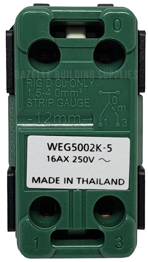
Pin Configuration and Descriptions

Pin Number Description Notes
1 Common Terminal Connects to the live wire or the load
2 Traveler Terminal 1 Interchangeable with Pin 3
3 Traveler Terminal 2 Interchangeable with Pin 2

Note: The traveler terminals are used to connect the switch to another 3-way switch, allowing for control of the load from two locations.

Usage Instructions

Wiring the 3-Way Switch

  1. Turn Off Power: Ensure that the power supply to the circuit is turned off at the breaker box to prevent electric shock.
  2. Identify Wires: Locate the common wire (usually marked or a different color) and the traveler wires in your electrical box.
  3. Connect Common Wire: Attach the common wire to the common terminal of the switch (Pin 1).
  4. Connect Traveler Wires: Connect the two traveler wires to the traveler terminals (Pins 2 and 3). The order does not matter.
  5. Grounding: If available, connect the ground wire to the grounding screw on the switch.
  6. Mount Switch: Secure the switch in the electrical box and attach the faceplate.
  7. Test the Circuit: Turn the power back on and test the switch from both locations to ensure proper operation.

Best Practices

  • Always follow local electrical codes and regulations.
  • Use a voltage tester to confirm power is off before working on the circuit.
  • Ensure wire connections are tight and secure.
  • Use wire nuts or electrical tape to cover any exposed wire connections outside of the switch terminals.

Troubleshooting and FAQs

Common Issues

  • Light Does Not Turn On: Check the connections at both switches and the light fixture. Ensure the common and traveler wires are correctly connected.
  • Switch Only Works from One Location: This usually indicates that the traveler wires are not connected properly. Verify that the traveler wires are connected to the correct terminals.

FAQs

Q: Can I use a 3-way switch as a single-pole switch? A: Yes, you can use a 3-way switch as a single-pole switch by using only the common terminal and one of the traveler terminals.

Q: What happens if I mix up the traveler wires? A: Mixing up the traveler wires will not harm the circuit, but the switches may not operate correctly. Ensure the traveler wires are connected to the correct terminals as per the wiring diagram.

Q: Can I use a 3-way switch with an Arduino UNO? A: While it's not a common application, you can use a 3-way switch with an Arduino UNO to detect switch positions. You would treat it like a regular switch in your code.

Example Arduino Code

// Define the pin connected to the common terminal of the switch
const int switchPin = 2;

void setup() {
  pinMode(switchPin, INPUT_PULLUP); // Enable internal pull-up resistor
  Serial.begin(9600);
}

void loop() {
  int switchState = digitalRead(switchPin);
  // Output the state of the switch: LOW when the switch is closed
  Serial.println(switchState);
  delay(500); // Debounce delay
}

Note: In this example, the Arduino's internal pull-up resistor is used, so the switch should connect to ground when activated. The serial output will show 0 when the switch is in the position connecting the common terminal to the switch pin.

This documentation provides a comprehensive overview of the 3-way switch, including its technical specifications, usage instructions, and troubleshooting tips. Always ensure safety by following proper electrical standards and practices.