How to Use PiggyMeter: Examples, Pinouts, and Specs
Introduction
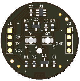
The PiggyMeter by Aquaticus (Manufacturer Part ID: IEC62056-21 Optical Interface) is a versatile digital multimeter designed for precise measurement of electrical parameters such as voltage, current, and resistance. It is equipped with a user-friendly interface and advanced features like data logging and connectivity options, making it suitable for both hobbyists and professionals. The PiggyMeter is particularly useful in applications requiring accurate monitoring and analysis of electrical systems.
Explore Projects Built with PiggyMeter
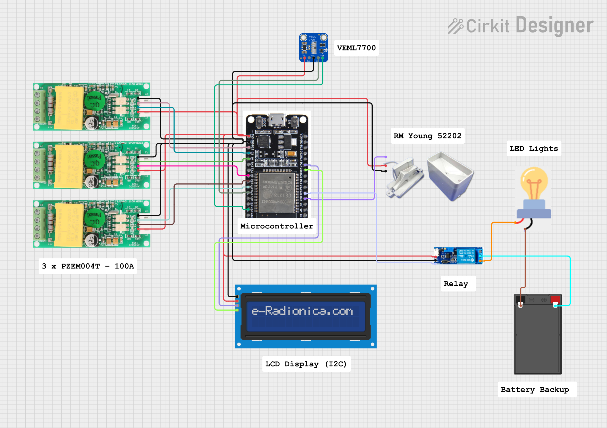
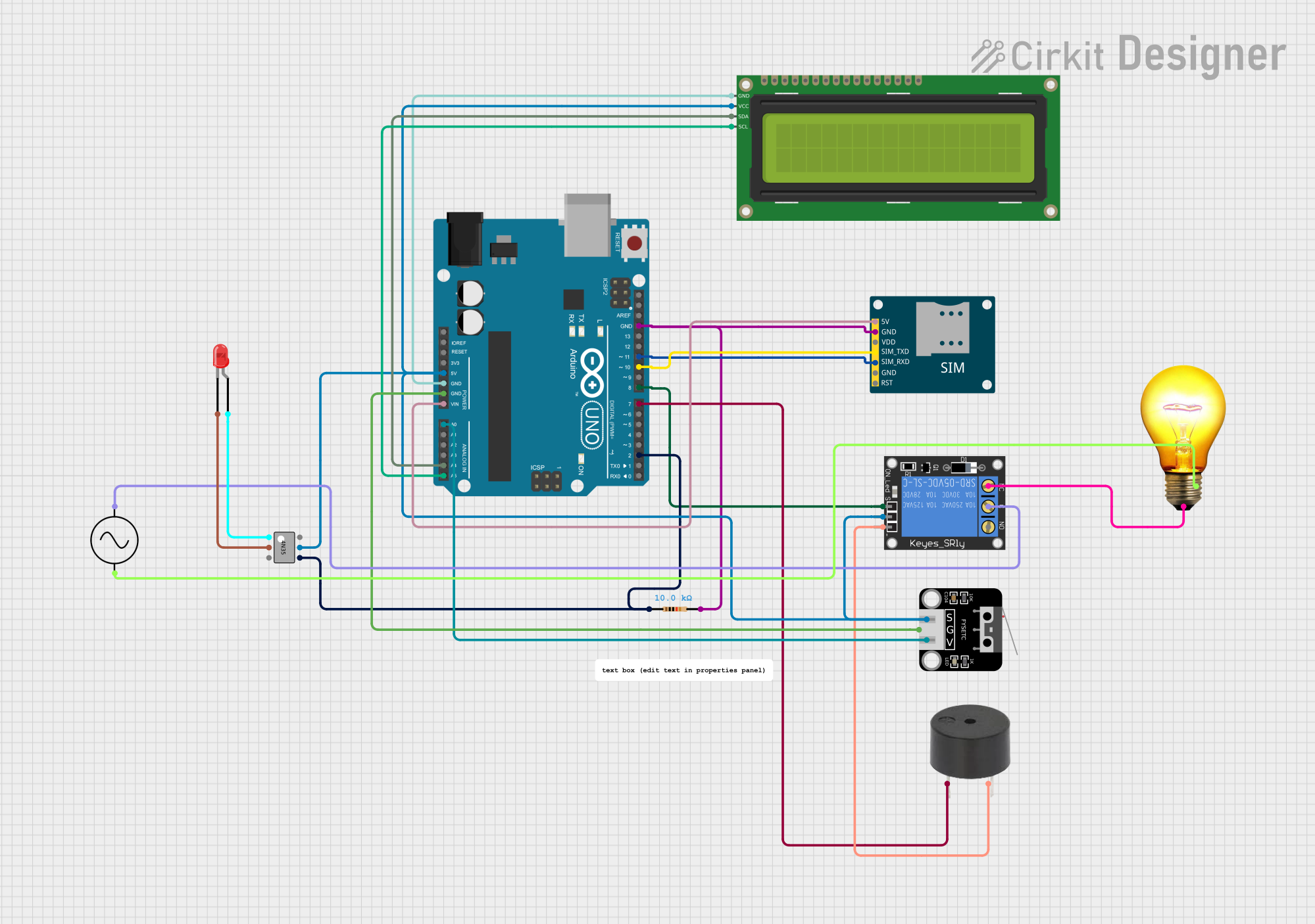
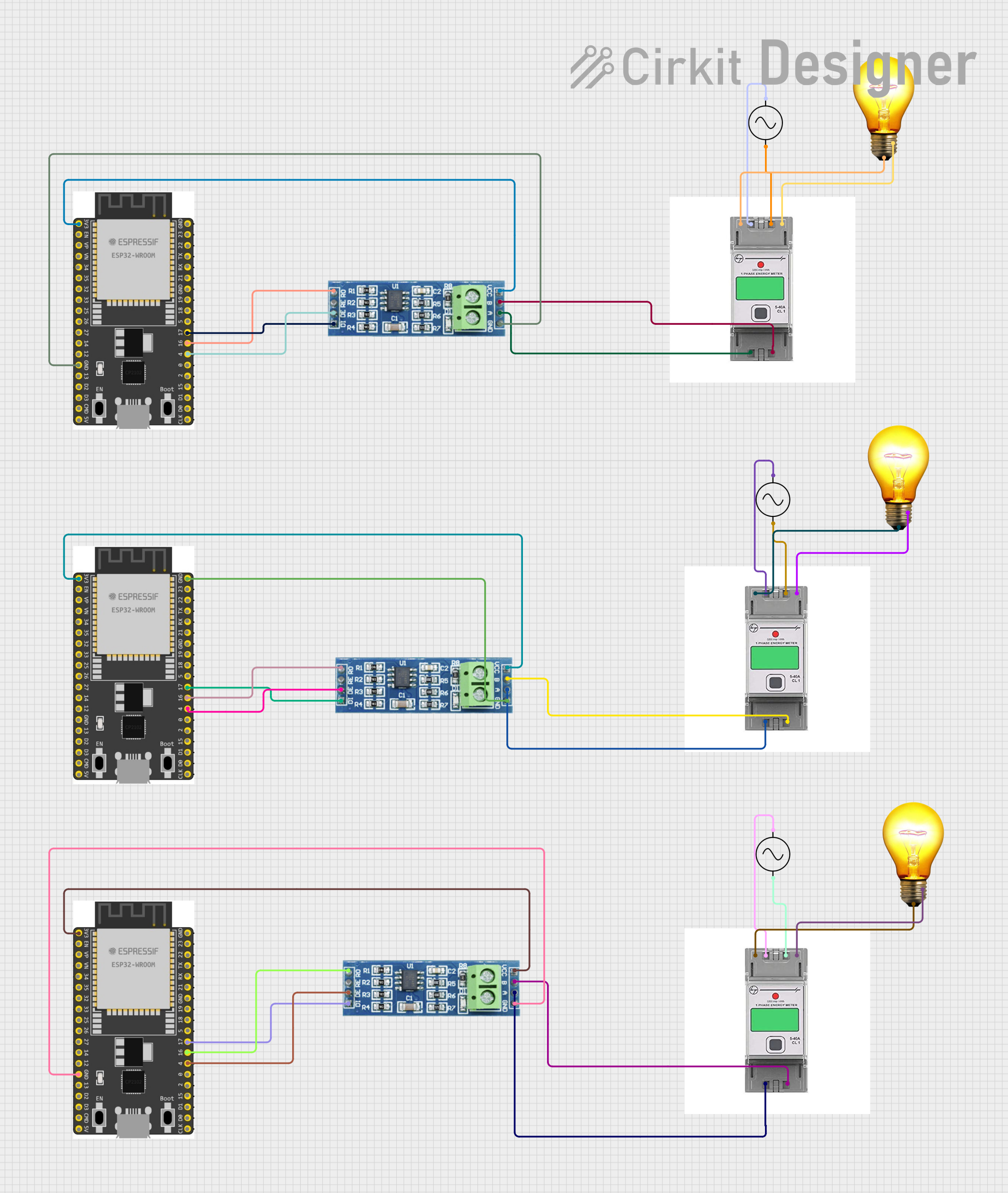

Explore Projects Built with PiggyMeter
Common Applications and Use Cases
- Electrical circuit testing and troubleshooting
- Monitoring power supply performance
- Data logging for research and development
- Educational purposes in electronics labs
- Industrial equipment maintenance and diagnostics
Technical Specifications
The PiggyMeter is designed to meet the needs of a wide range of users, offering robust performance and reliability. Below are its key technical specifications:
General Specifications
| Parameter | Value |
|---|---|
| Manufacturer | Aquaticus |
| Part ID | IEC62056-21 Optical Interface |
| Measurement Modes | Voltage, Current, Resistance |
| Display Type | Digital LCD with backlight |
| Connectivity Options | Optical interface, USB |
| Data Logging Capability | Yes |
| Power Supply | 9V battery or USB power |
| Dimensions | 150mm x 75mm x 30mm |
| Weight | 250g |
Measurement Ranges and Accuracy
| Measurement Type | Range | Accuracy |
|---|---|---|
| Voltage (DC) | 0 - 600V | ±0.5% + 2 digits |
| Voltage (AC) | 0 - 600V | ±1.0% + 3 digits |
| Current (DC) | 0 - 10A | ±1.0% + 2 digits |
| Current (AC) | 0 - 10A | ±1.5% + 3 digits |
| Resistance | 0 - 40MΩ | ±1.0% + 2 digits |
Pin Configuration and Descriptions
| Pin Name | Description |
|---|---|
| COM | Common ground terminal for all measurements |
| VΩmA | Input terminal for voltage, resistance, and low- |
| current measurements (up to 200mA) | |
| 10A | Dedicated input terminal for high-current |
| measurements (up to 10A) |
Usage Instructions
The PiggyMeter is designed for ease of use, but proper handling is essential to ensure accurate measurements and safety. Follow the steps below to use the PiggyMeter effectively:
Basic Operation
- Power On: Insert a 9V battery or connect the PiggyMeter to a USB power source. Turn the rotary switch to the desired measurement mode (e.g., voltage, current, resistance).
- Connect Probes: Insert the black probe into the
COMterminal and the red probe into the appropriate terminal (VΩmAfor most measurements or10Afor high-current measurements). - Select Range: If the PiggyMeter is not auto-ranging, manually select the appropriate range for the measurement.
- Take Measurement: Connect the probes to the circuit or component under test. Read the measurement on the LCD display.
Important Considerations
- Always start with the highest range when measuring an unknown parameter to avoid damaging the device.
- Do not exceed the maximum input ratings for voltage, current, or resistance.
- Use the optical interface or USB connection to transfer data to a computer for logging or analysis.
- Ensure the device is powered off when not in use to conserve battery life.
Example: Using the PiggyMeter with an Arduino UNO
The PiggyMeter can be used to measure voltage or current in circuits involving an Arduino UNO. Below is an example of measuring the voltage across a resistor in a simple LED circuit.
Arduino Code
// Simple LED circuit example for voltage measurement
// Connect the PiggyMeter probes across the resistor to measure voltage.

const int ledPin = 9; // Pin connected to the LED
void setup() {
  pinMode(ledPin, OUTPUT); // Set the LED pin as output
}

void loop() {
  digitalWrite(ledPin, HIGH); // Turn the LED on
  delay(1000);                // Wait for 1 second
  digitalWrite(ledPin, LOW);  // Turn the LED off
  delay(1000);                // Wait for 1 second
}
Measurement Steps
- Build the circuit with the Arduino UNO, LED, and resistor.
- Set the PiggyMeter to DC voltage mode.
- Connect the probes across the resistor.
- Observe the voltage reading on the PiggyMeter display.
Troubleshooting and FAQs
Common Issues and Solutions
| Issue | Possible Cause | Solution |
|---|---|---|
| No display on the screen | Battery is dead or not installed | Replace or install a 9V battery |
| Incorrect readings | Probes connected to wrong terminals | Verify probe connections |
| Overload (OL) displayed | Measurement range exceeded | Select a higher range |
| Data not transferring to PC | Faulty USB or optical connection | Check cables and ensure drivers are |
| installed |
FAQs
Q: Can the PiggyMeter measure AC current?
A: Yes, the PiggyMeter can measure AC current up to 10A using the 10A terminal.
Q: How do I enable data logging?
A: Use the optical interface or USB connection to connect the PiggyMeter to a computer. Install the Aquaticus software to enable data logging.
Q: Is the PiggyMeter suitable for high-voltage applications?
A: The PiggyMeter can measure voltages up to 600V. For higher voltages, use appropriate step-down circuits or equipment.
By following this documentation, users can maximize the functionality and lifespan of their PiggyMeter while ensuring safe and accurate measurements.