
How to Use 7-SEGMENT-4DIGIT: Examples, Pinouts, and Specs

 Design with 7-SEGMENT-4DIGIT in Cirkit Designer
Introduction
The 7-SEGMENT-4DIGIT display is a versatile electronic component designed to visually represent decimal numbers. It consists of four individual 7-segment digits, each made up of seven LED segments arranged in a figure-eight pattern. By illuminating specific segments, the display can represent numbers from 0 to 9.
This component is widely used in digital clocks, counters, timers, and other devices requiring numeric displays. Its compact design and ease of use make it a popular choice for both hobbyists and professionals.
Explore Projects Built with 7-SEGMENT-4DIGIT
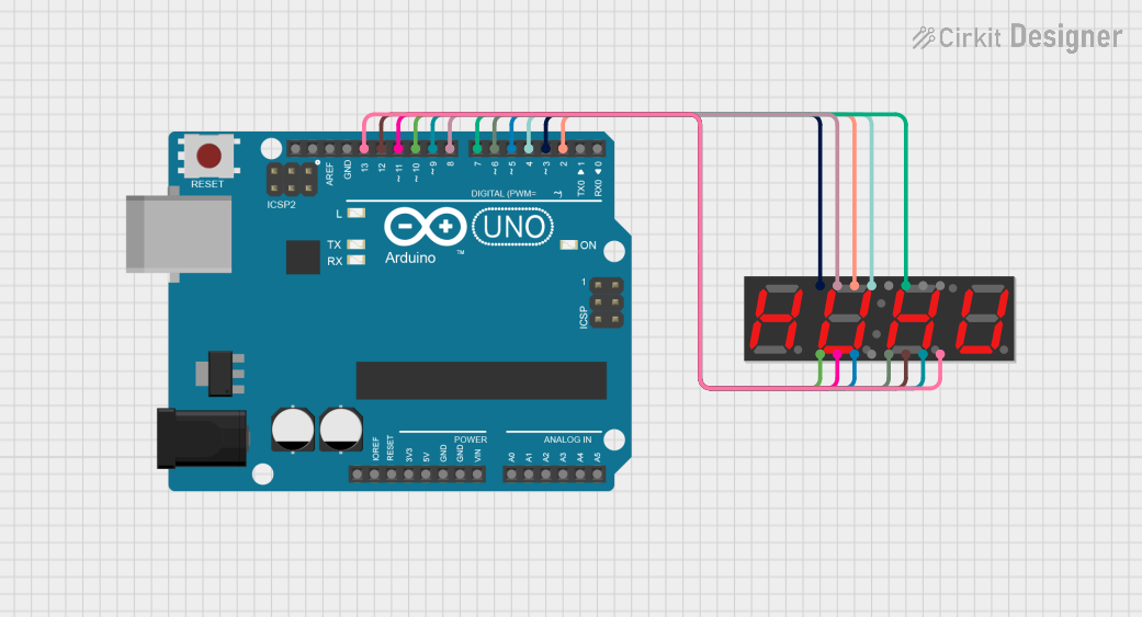 Open Project in Cirkit Designer
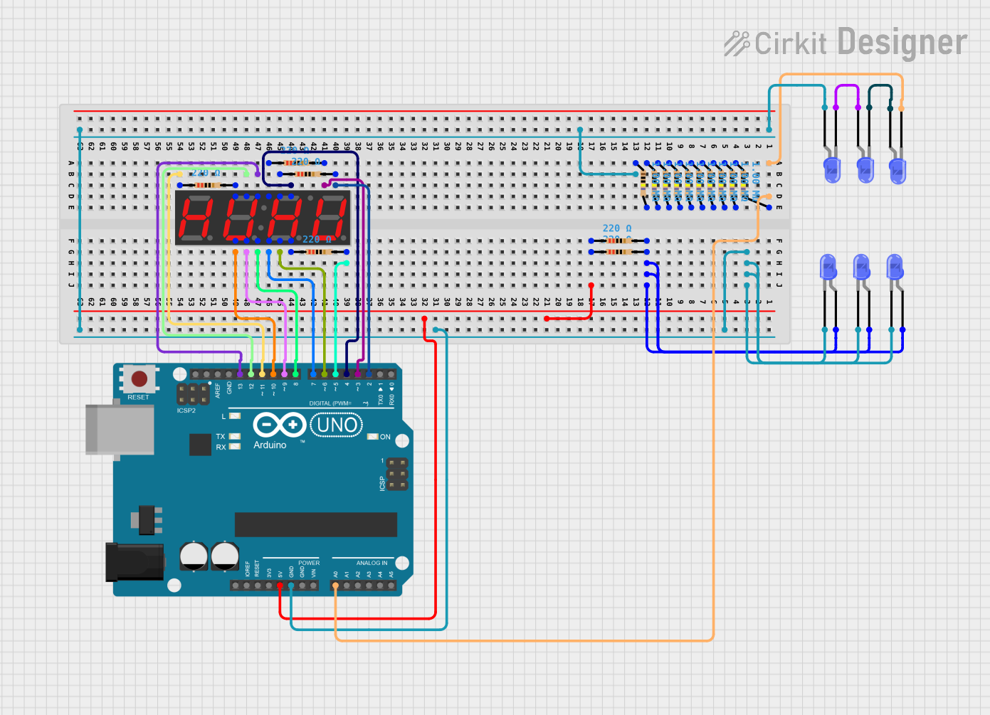 Open Project in Cirkit Designer
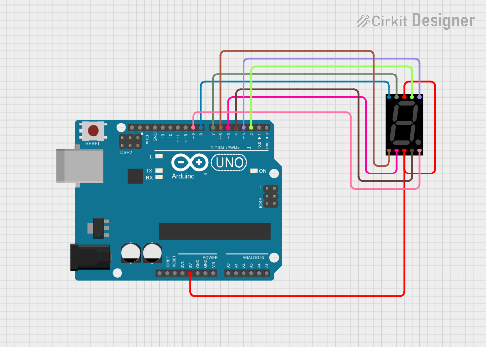 Open Project in Cirkit Designer
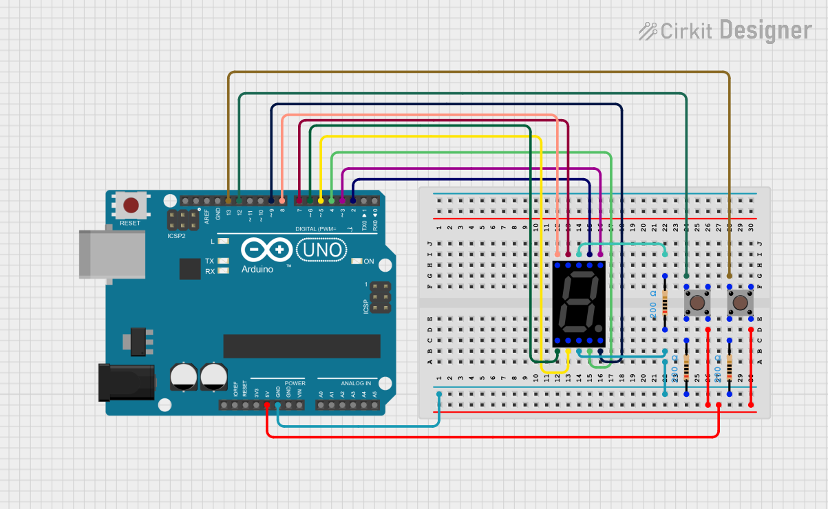 Open Project in Cirkit Designer
Explore Projects Built with 7-SEGMENT-4DIGIT
Open Project in Cirkit DesignerOpen Project in Cirkit DesignerOpen Project in Cirkit DesignerOpen Project in Cirkit DesignerTechnical Specifications
- Type: 4-digit 7-segment display
- Operating Voltage: Typically 3.3V to 5V (check specific model datasheet)
- Current Consumption: ~20mA per segment (varies by model)
- Display Type: Common Cathode or Common Anode (varies by model)
- Segment LEDs: 7 segments per digit + 1 decimal point per digit
- Dimensions: Varies by model (e.g., 50mm x 20mm x 10mm)
Pin Configuration and Descriptions
The 7-SEGMENT-4DIGIT display typically has 12 or more pins. Below is a general pinout for a common cathode display:
| Pin Number | Label | Description |
|---|---|---|
| 1 | A | Segment A control |
| 2 | B | Segment B control |
| 3 | C | Segment C control |
| 4 | D | Segment D control |
| 5 | E | Segment E control |
| 6 | F | Segment F control |
| 7 | G | Segment G control |
| 8 | DP | Decimal Point control |
| 9 | DIG1 | Common cathode/anode for digit 1 |
| 10 | DIG2 | Common cathode/anode for digit 2 |
| 11 | DIG3 | Common cathode/anode for digit 3 |
| 12 | DIG4 | Common cathode/anode for digit 4 |
Note: The exact pin configuration may vary depending on the manufacturer. Always refer to the datasheet for your specific model.
Usage Instructions
How to Use the Component in a Circuit
- Determine the Type: Identify whether your display is common cathode or common anode. This will affect how you connect it to your circuit.
- For common cathode, connect the cathode pins (DIG1–DIG4) to ground.
- For common anode, connect the anode pins (DIG1–DIG4) to the positive voltage supply.
- Connect the Segments: Use current-limiting resistors (typically 220Ω to 1kΩ) between the segment pins (A–G, DP) and your microcontroller or driver IC to prevent overcurrent.
- Control the Digits: Use multiplexing to control which digit is active at any given time. This reduces the number of pins required for control.
Example: Connecting to an Arduino UNO
Below is an example of how to connect and control a 7-SEGMENT-4DIGIT display using an Arduino UNO. This example assumes a common cathode display.
Circuit Connections
- Connect segment pins (A–G, DP) to Arduino digital pins (e.g., D2–D9) through 220Ω resistors.
- Connect DIG1–DIG4 to Arduino digital pins (e.g., D10–D13).
- Connect the common cathode pins (DIG1–DIG4) to ground via NPN transistors for multiplexing.
Arduino Code
// Define segment pins
const int segmentPins[] = {2, 3, 4, 5, 6, 7, 8, 9}; // A, B, C, D, E, F, G, DP
// Define digit control pins
const int digitPins[] = {10, 11, 12, 13}; // DIG1, DIG2, DIG3, DIG4

// Digit patterns for numbers 0-9 (common cathode)
const byte digitPatterns[] = {
  0b00111111, // 0
  0b00000110, // 1
  0b01011011, // 2
  0b01001111, // 3
  0b01100110, // 4
  0b01101101, // 5
  0b01111101, // 6
  0b00000111, // 7
  0b01111111, // 8
  0b01101111  // 9
};

void setup() {
  // Set segment pins as outputs
  for (int i = 0; i < 8; i++) {
    pinMode(segmentPins[i], OUTPUT);
  }
  // Set digit pins as outputs
  for (int i = 0; i < 4; i++) {
    pinMode(digitPins[i], OUTPUT);
  }
}

void loop() {
  // Display the number "1234"
  displayNumber(1234);
}

void displayNumber(int number) {
  for (int digit = 0; digit < 4; digit++) {
    // Extract the digit to display
    int digitValue = (number / (int)pow(10, digit)) % 10;

    // Set the segments for the current digit
    setSegments(digitPatterns[digitValue]);

    // Activate the current digit
    digitalWrite(digitPins[digit], LOW); // Turn on digit (common cathode)
    delay(5); // Small delay for persistence of vision
    digitalWrite(digitPins[digit], HIGH); // Turn off digit
  }
}

void setSegments(byte pattern) {
  for (int i = 0; i < 8; i++) {
    digitalWrite(segmentPins[i], (pattern >> i) & 0x01);
  }
}
Important Considerations and Best Practices
- Use Resistors: Always use current-limiting resistors to protect the LEDs from overcurrent.
- Multiplexing: To reduce power consumption and pin usage, use multiplexing techniques.
- Brightness Control: Use PWM (Pulse Width Modulation) on the digit control pins to adjust brightness.
Troubleshooting and FAQs
Common Issues
- Segments Not Lighting Up:
- Check the connections and ensure the correct pins are connected.
- Verify that the resistors are not too high, which could limit current excessively.
- Incorrect Digits Displayed:
- Ensure the correct digit patterns are being sent to the segments.
- Double-check the wiring for segment pins.
- Flickering Display:
- Increase the refresh rate in the multiplexing code.
- Ensure proper grounding and stable power supply.
FAQs
Q: Can I use this display with a 3.3V microcontroller?
A: Yes, but ensure the forward voltage of the LEDs is compatible with 3.3V. You may need to adjust resistor values accordingly.
Q: How do I know if my display is common cathode or common anode?
A: Refer to the datasheet or test the display by connecting a single segment to power and ground.
Q: Can I control this display without multiplexing?
A: Yes, but it would require a large number of GPIO pins or an external driver IC like the MAX7219.
By following this documentation, you can effectively integrate and troubleshoot the 7-SEGMENT-4DIGIT display in your projects.