How to Use Adafruit bq25185 USB / DC / Solar Charger with 3.3V Buck Board: Examples, Pinouts, and Specs
Introduction
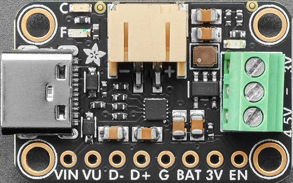
The Adafruit bq25185 USB / DC / Solar Charger with 3.3V Buck Board (Part ID: ADA6092) is a versatile and compact power management module designed for efficient charging and voltage regulation. It supports multiple power input sources, including USB, DC, and solar panels, making it ideal for portable and renewable energy projects. The integrated 3.3V buck converter ensures stable voltage output for powering low-power microcontrollers, sensors, and other electronics.
Explore Projects Built with Adafruit bq25185 USB / DC / Solar Charger with 3.3V Buck Board
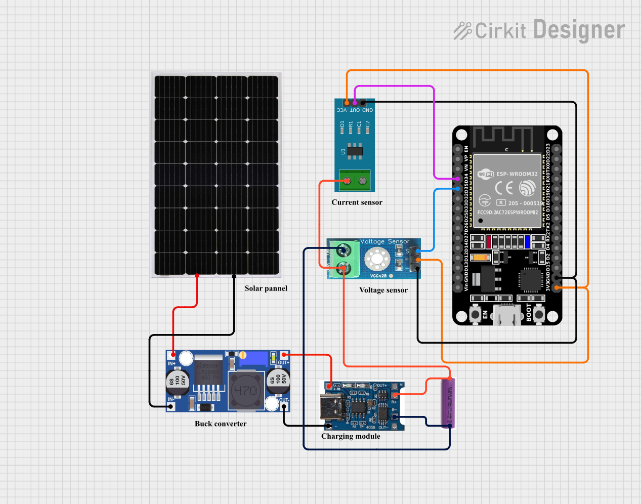
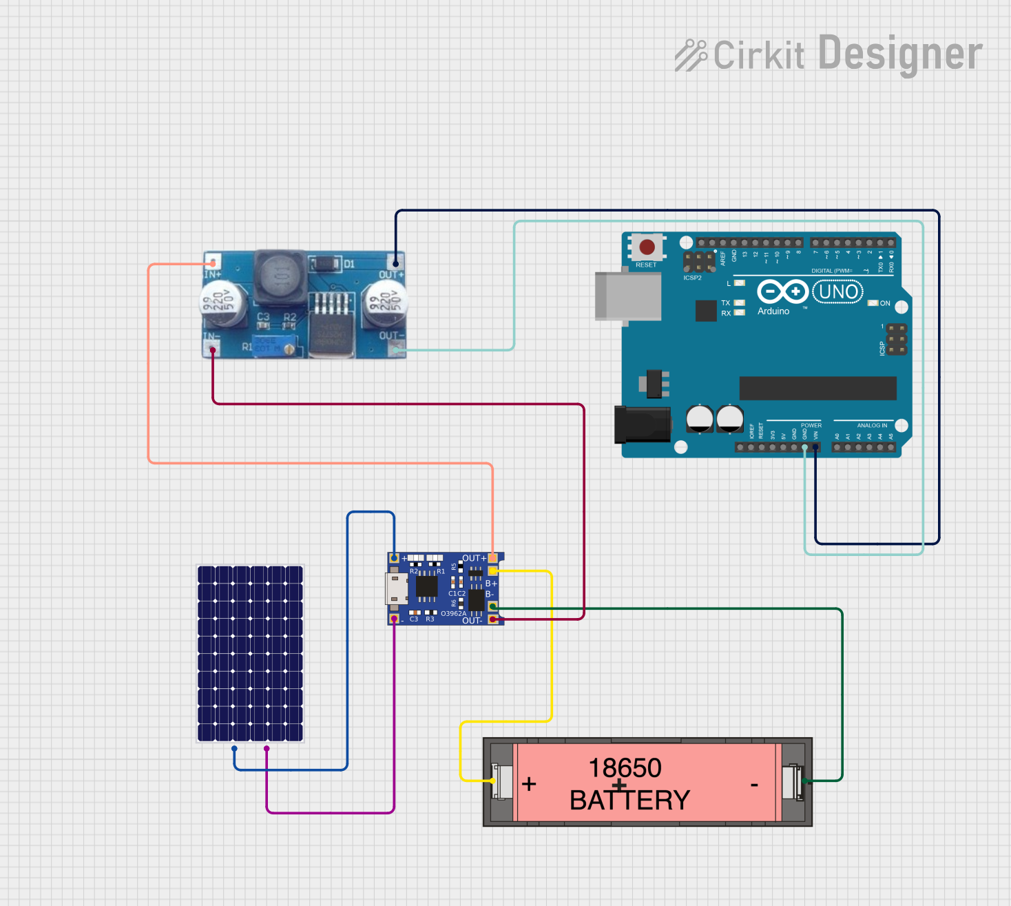
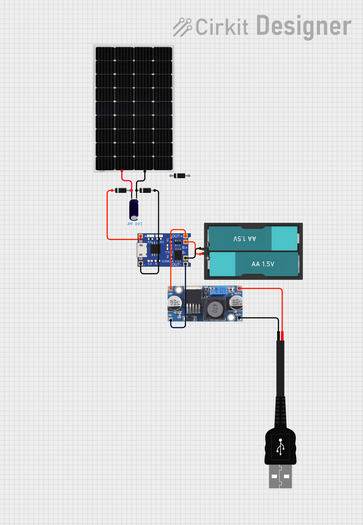

Explore Projects Built with Adafruit bq25185 USB / DC / Solar Charger with 3.3V Buck Board
Common Applications and Use Cases
- Solar-powered IoT devices
- Battery-powered embedded systems
- Wearable electronics
- Low-power microcontroller projects
- Portable power banks and chargers
Technical Specifications
Key Technical Details
| Parameter | Value |
|---|---|
| Input Voltage Range | 4.2V to 17V |
| Output Voltage (Buck) | 3.3V (regulated) |
| Maximum Output Current | 1A (buck converter) |
| Battery Charging Voltage | Configurable (default: 4.2V for LiPo) |
| Battery Charging Current | Configurable up to 500mA |
| Power Input Sources | USB, DC, Solar |
| Battery Type Supported | Single-cell LiPo/Li-Ion |
| Operating Temperature | -40°C to +85°C |
| Dimensions | 25mm x 25mm |
Pin Configuration and Descriptions
| Pin Name | Description |
|---|---|
| VIN | Main power input (4.2V to 17V). Connect USB, DC, or solar panel here. |
| GND | Ground connection. |
| BAT | Battery connection for a single-cell LiPo/Li-Ion battery. |
| 3V3 | Regulated 3.3V output from the buck converter. |
| EN | Enable pin for the buck converter. Pull low to disable the 3.3V output. |
| STAT | Status pin for battery charging (low = charging, high = fully charged). |
| PG | Power Good indicator (high = input power is good). |
| ISET | Current set pin for configuring the charging current. |
| TS | Temperature sense pin for battery thermistor (optional). |
Usage Instructions
How to Use the Component in a Circuit
- Power Input: Connect your power source (USB, DC, or solar panel) to the
VINpin. Ensure the input voltage is within the range of 4.2V to 17V. - Battery Connection: Attach a single-cell LiPo/Li-Ion battery to the
BATpin. The module will automatically manage charging. - 3.3V Output: Use the
3V3pin to power your 3.3V devices. Ensure the total current draw does not exceed 1A. - Enable Pin: If you need to disable the 3.3V output, pull the
ENpin low. - Charging Current Configuration: Use the
ISETpin to set the desired charging current. Refer to the datasheet for resistor values corresponding to specific currents. - Temperature Monitoring: Optionally, connect a thermistor to the
TSpin for battery temperature monitoring.
Important Considerations and Best Practices
- Battery Safety: Always use a compatible single-cell LiPo/Li-Ion battery. Ensure the battery has built-in protection circuitry.
- Heat Dissipation: The module may heat up during operation, especially at high input voltages or charging currents. Ensure adequate ventilation.
- Solar Panel Use: When using a solar panel, ensure it provides sufficient voltage and current under typical lighting conditions.
- Power Good Indicator: Use the
PGpin to monitor the availability of input power for system diagnostics.
Example: Connecting to an Arduino UNO
The 3.3V output of the module can be used to power an Arduino UNO or other 3.3V-compatible devices. Below is an example of how to monitor the charging status using the STAT pin.
// Example code to monitor charging status using the STAT pin
const int statPin = 2; // STAT pin connected to digital pin 2

void setup() {
  pinMode(statPin, INPUT);
  Serial.begin(9600);
}

void loop() {
  int chargingStatus = digitalRead(statPin);

  if (chargingStatus == LOW) {
    // STAT pin is LOW when charging
    Serial.println("Battery is charging...");
  } else {
    // STAT pin is HIGH when fully charged
    Serial.println("Battery is fully charged.");
  }

  delay(1000); // Wait for 1 second before checking again
}
Troubleshooting and FAQs
Common Issues and Solutions
Module Overheating
- Cause: High input voltage or excessive charging current.
- Solution: Reduce the input voltage or configure a lower charging current using the
ISETpin.
Battery Not Charging
- Cause: Incorrect battery connection or incompatible battery type.
- Solution: Verify the battery polarity and ensure it is a single-cell LiPo/Li-Ion battery.
No 3.3V Output
- Cause:
ENpin is pulled low or no input power. - Solution: Check the
ENpin state and ensure a valid power source is connected toVIN.
- Cause:
Solar Panel Not Providing Power
- Cause: Insufficient sunlight or low panel output voltage.
- Solution: Test the solar panel under direct sunlight and ensure it meets the input voltage requirements.
FAQs
Q: Can I use this module with a 5V USB power source?
A: Yes, the module is compatible with 5V USB power sources. Ensure the input voltage is within the 4.2V to 17V range.
Q: What happens if the battery is disconnected?
A: The module will continue to provide a 3.3V output from the buck converter as long as a valid input power source is connected.
Q: Can I use this module to charge other types of batteries?
A: No, this module is specifically designed for single-cell LiPo/Li-Ion batteries. Using other battery types may result in damage or unsafe operation.
Q: How do I adjust the charging current?
A: Use a resistor on the ISET pin to configure the charging current. Refer to the datasheet for the appropriate resistor values.
This concludes the documentation for the Adafruit bq25185 USB / DC / Solar Charger with 3.3V Buck Board. For further assistance, refer to the official Adafruit resources or community forums.