How to Use STA540: Examples, Pinouts, and Specs
Introduction
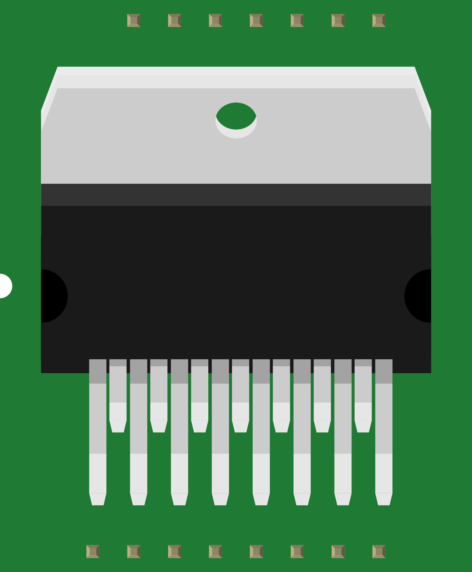
The STA540 is a monolithic quad half-bridge stage in Multiwatt15 package designed for audio amplification. It is capable of delivering up to 38W of continuous average power to an 8Ω load with less than 10% THD+N from a 22V supply, and 35W into 4Ω in single-ended mode. This component is widely used in applications such as mini component systems, self-powered speakers, and stereo amplifiers. Its high-quality audio amplification with low distortion and low power consumption makes it a popular choice for high-fidelity audio systems.
Explore Projects Built with STA540


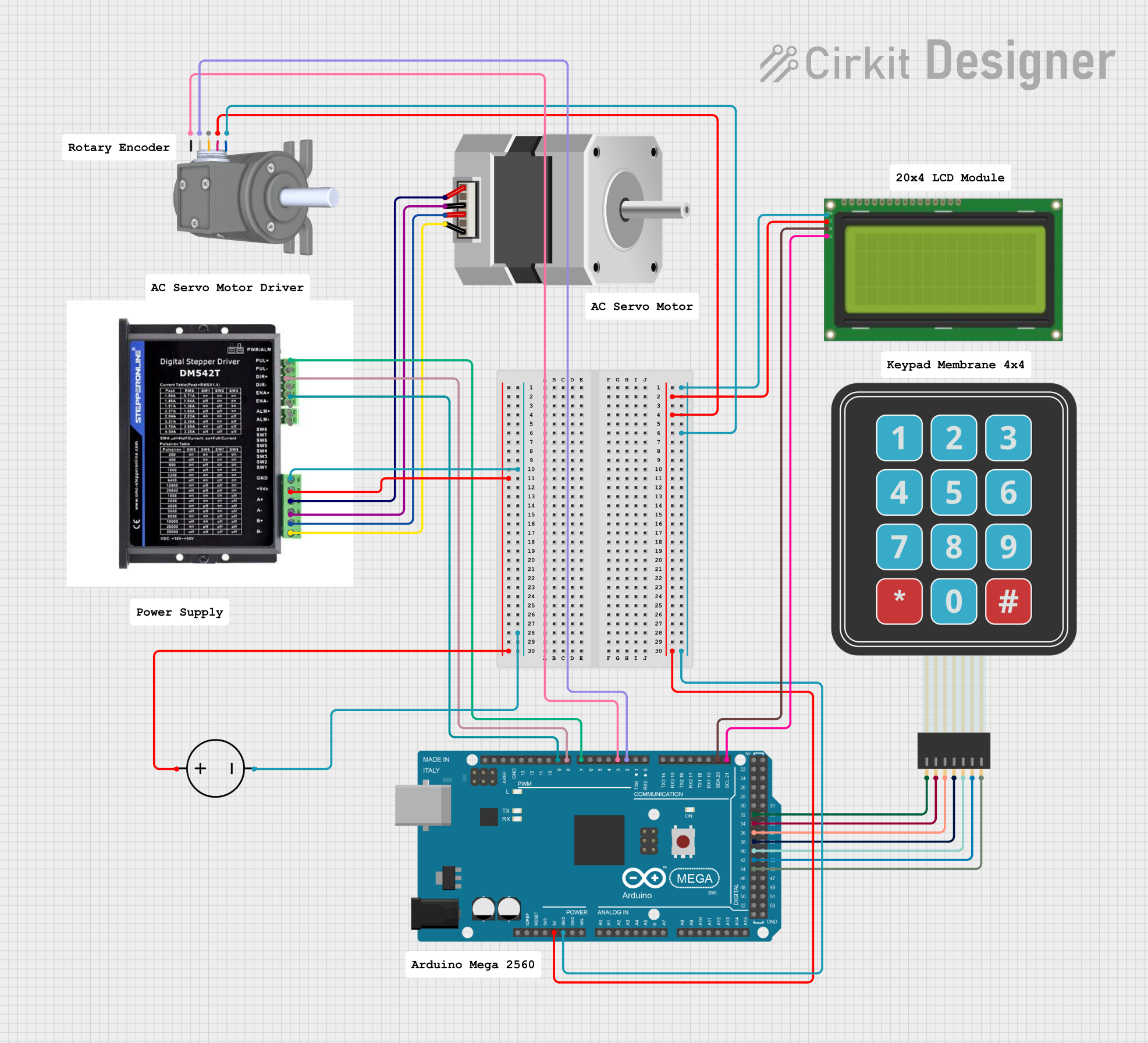

Explore Projects Built with STA540
Common Applications
- Mini component audio systems
- Self-powered speakers
- Stereo amplifiers
- Home theater systems
- Active loudspeakers
Technical Specifications
Key Technical Details
- Power Output: Up to 38W per channel into 8Ω at 22V supply
- Operating Voltage Range: 8V - 22V
- Standby Current: Max 80µA
- Signal-to-Noise Ratio: 100 dB (typical)
- Number of Channels: 4 (can be configured as 2 BTL channels)
Pin Configuration and Descriptions
| Pin Number | Pin Name | Description |
|---|---|---|
| 1 | OUT1 | Output of channel 1 |
| 2 | SVRR | Supply voltage rejection |
| 3 | IN1 | Input of channel 1 |
| 4 | ST-BY | Standby control pin (active low) |
| 5 | IN2 | Input of channel 2 |
| 6 | OUT2 | Output of channel 2 |
| 7 | GND | Ground reference |
| 8 | VCC | Supply voltage |
| 9 | OUT3 | Output of channel 3 |
| 10 | IN3 | Input of channel 3 |
| 11 | IN4 | Input of channel 4 |
| 12 | OUT4 | Output of channel 4 |
| 13 | BOOT4 | Bootstrap capacitor connection for channel 4 |
| 14 | BOOT3 | Bootstrap capacitor connection for channel 3 |
| 15 | D95V | Diagnostic output for 95V |
Usage Instructions
How to Use the STA540 in a Circuit
Power Supply: Ensure that the power supply voltage is within the specified range (8V - 22V). Exceeding the voltage range can damage the STA540.
Input Signal: Connect the audio input signal to the IN1 and IN2 pins for stereo operation. For bridge-tied load (BTL) configuration, use IN1/IN3 and IN2/IN4.
Output Connection: Connect the OUT1 and OUT2 pins to the speakers. Ensure that the speaker impedance matches the STA540's specifications.
Standby Mode: The ST-BY pin can be used to switch the STA540 into standby mode to save power. Connect this pin to ground to activate the amplifier.
Heat Dissipation: The STA540 can generate significant heat during operation. Ensure proper heat sinking to maintain thermal stability.
Best Practices
- Use decoupling capacitors close to the power supply pins to minimize power supply noise.
- Keep audio input lines as short as possible to reduce the risk of picking up interference.
- Ensure proper grounding to prevent hum and noise in the audio output.
- Use a proper filter at the output to prevent RF interference from affecting the audio signal.
Troubleshooting and FAQs
Common Issues
- No Sound Output: Check power supply connections, input signal presence, and speaker connections.
- Distorted Sound: Ensure that the input signal level is not too high, causing clipping. Also, check for proper power supply voltage and heat dissipation.
- Overheating: If the STA540 is overheating, improve heat sinking, check for short circuits, and ensure the load impedance is not too low.
Solutions and Tips
- Low Output Volume: Increase the input signal level or check for incorrect gain settings.
- Hum or Noise: Verify grounding and input signal shielding. Use decoupling capacitors as recommended.
- Intermittent Sound: Check for loose connections or cold solder joints.
FAQs
Q: Can the STA540 be used in a mono configuration? A: Yes, the STA540 can be configured in a mono Bridge-Tied Load (BTL) mode for higher power output.
Q: What is the standby current of the STA540? A: The standby current is typically around 80µA.
Q: How can I improve the sound quality of my amplifier using the STA540? A: Use high-quality input sources, ensure proper layout and grounding, and use appropriate filtering on the output.
Q: Is it necessary to use a heatsink with the STA540? A: Yes, due to the power dissipation during operation, a heatsink is recommended to maintain thermal stability.
For any further assistance or detailed application notes, please refer to the manufacturer's datasheet and application guidelines.