
How to Use SPDT Switch: Examples, Pinouts, and Specs
 Design with SPDT Switch in Cirkit Designer
Introduction
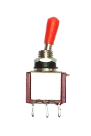
A Single Pole Double Throw (SPDT) switch is an electrical switch that allows a single input to connect to one of two outputs. This functionality enables the selection between two different circuits or devices. SPDT switches are versatile and commonly used in applications requiring circuit selection, signal routing, or toggling between two states.
Explore Projects Built with SPDT Switch
 Open Project in Cirkit Designer
 Open Project in Cirkit Designer
 Open Project in Cirkit Designer
 Open Project in Cirkit Designer
Explore Projects Built with SPDT Switch
Open Project in Cirkit DesignerOpen Project in Cirkit DesignerOpen Project in Cirkit DesignerOpen Project in Cirkit DesignerCommon Applications and Use Cases
- Switching between two power sources (e.g., battery and external power).
- Selecting between two signal paths in audio or communication systems.
- Controlling devices in home automation systems.
- Used in robotics for toggling between different motor directions.
- Implemented in test equipment for signal routing.
Technical Specifications
Below are the general technical specifications for a typical SPDT switch. Note that specific values may vary depending on the manufacturer and model.
| Parameter | Specification |
|---|---|
| Switch Type | Single Pole Double Throw (SPDT) |
| Voltage Rating | 3V to 250V (varies by model) |
| Current Rating | 0.5A to 15A (varies by model) |
| Contact Resistance | < 50 mΩ |
| Insulation Resistance | > 100 MΩ |
| Mechanical Life | 10,000 to 100,000 cycles |
| Operating Temperature | -40°C to +85°C |
Pin Configuration and Descriptions
An SPDT switch typically has three terminals:
| Pin Name | Description |
|---|---|
| Common (C) | The input terminal that connects to one of the two output terminals. |
| Normally Open (NO) | The terminal that connects to the common terminal when the switch is activated. |
| Normally Closed (NC) | The terminal that connects to the common terminal when the switch is not activated. |
Usage Instructions
How to Use the SPDT Switch in a Circuit
- Identify the Terminals: Locate the Common (C), Normally Open (NO), and Normally Closed (NC) terminals on the switch.
- Connect the Common Terminal: Attach the input signal or power source to the Common (C) terminal.
- Connect the Output Terminals:
- Connect the first output circuit to the Normally Open (NO) terminal.
- Connect the second output circuit to the Normally Closed (NC) terminal.
- Toggle the Switch: Flip the switch to route the input signal to either the NO or NC terminal, depending on the desired output.
Important Considerations and Best Practices
- Voltage and Current Ratings: Ensure the switch's voltage and current ratings are suitable for your application to avoid damage or failure.
- Debouncing: When using the SPDT switch in digital circuits, consider implementing debouncing techniques to eliminate noise caused by mechanical contacts.
- Mounting: Secure the switch properly to prevent mechanical stress or accidental disconnection.
- Testing: Use a multimeter to verify the continuity between terminals before integrating the switch into your circuit.
Example: Connecting an SPDT Switch to an Arduino UNO
An SPDT switch can be used with an Arduino UNO to toggle between two LEDs. Below is an example circuit and code:
Circuit Connections
- Connect the Common (C) terminal of the SPDT switch to a digital input pin on the Arduino (e.g., pin 2).
- Connect the Normally Open (NO) terminal to one LED (with a current-limiting resistor) and the Normally Closed (NC) terminal to another LED.
- Connect the other ends of the LEDs to ground.
Arduino Code
// Define pin numbers for the SPDT switch and LEDs
const int switchPin = 2;  // SPDT switch common terminal connected to pin 2
const int led1Pin = 3;    // LED 1 connected to Normally Open (NO) terminal
const int led2Pin = 4;    // LED 2 connected to Normally Closed (NC) terminal

void setup() {
  pinMode(switchPin, INPUT_PULLUP); // Configure switch pin as input with pull-up resistor
  pinMode(led1Pin, OUTPUT);         // Configure LED 1 pin as output
  pinMode(led2Pin, OUTPUT);         // Configure LED 2 pin as output
}

void loop() {
  int switchState = digitalRead(switchPin); // Read the state of the SPDT switch

  if (switchState == LOW) {
    // If the switch is toggled to the Normally Open (NO) position
    digitalWrite(led1Pin, HIGH);  // Turn on LED 1
    digitalWrite(led2Pin, LOW);   // Turn off LED 2
  } else {
    // If the switch is toggled to the Normally Closed (NC) position
    digitalWrite(led1Pin, LOW);   // Turn off LED 1
    digitalWrite(led2Pin, HIGH);  // Turn on LED 2
  }
}
Troubleshooting and FAQs
Common Issues and Solutions
Switch Not Working as Expected:
- Cause: Incorrect wiring of the terminals.
- Solution: Double-check the connections to the Common (C), Normally Open (NO), and Normally Closed (NC) terminals.
Intermittent Behavior:
- Cause: Mechanical contact bounce.
- Solution: Implement software or hardware debouncing techniques.
LEDs Not Lighting Up in Arduino Circuit:
- Cause: Incorrect pin configuration or missing resistors.
- Solution: Verify the Arduino code and ensure current-limiting resistors are used with LEDs.
Switch Overheating:
- Cause: Exceeding the voltage or current rating of the switch.
- Solution: Use a switch with appropriate ratings for your application.
FAQs
Q: Can I use an SPDT switch to control AC devices?
A: Yes, as long as the switch's voltage and current ratings are suitable for the AC device.
Q: How do I debounce an SPDT switch?
A: You can use a capacitor and resistor in hardware or implement a software delay in your microcontroller code.
Q: What is the difference between SPDT and DPDT switches?
A: An SPDT switch has one input and two outputs, while a DPDT (Double Pole Double Throw) switch has two inputs and four outputs, allowing control of two separate circuits simultaneously.