How to Use Adafruit FONA 800 Shield: Examples, Pinouts, and Specs
Introduction
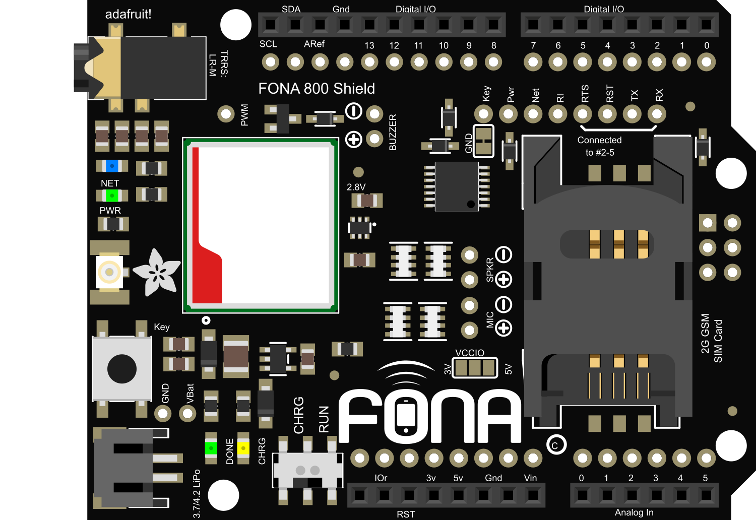
The Adafruit FONA 800 Shield is an invaluable addition to the Arduino ecosystem, providing GSM/GPRS functionality to your projects. This shield allows for cellular communication, enabling devices to make calls, send texts, and connect to the internet over a mobile network. It's perfect for remote monitoring, asset tracking, and any application where wireless communication is required.
Explore Projects Built with Adafruit FONA 800 Shield
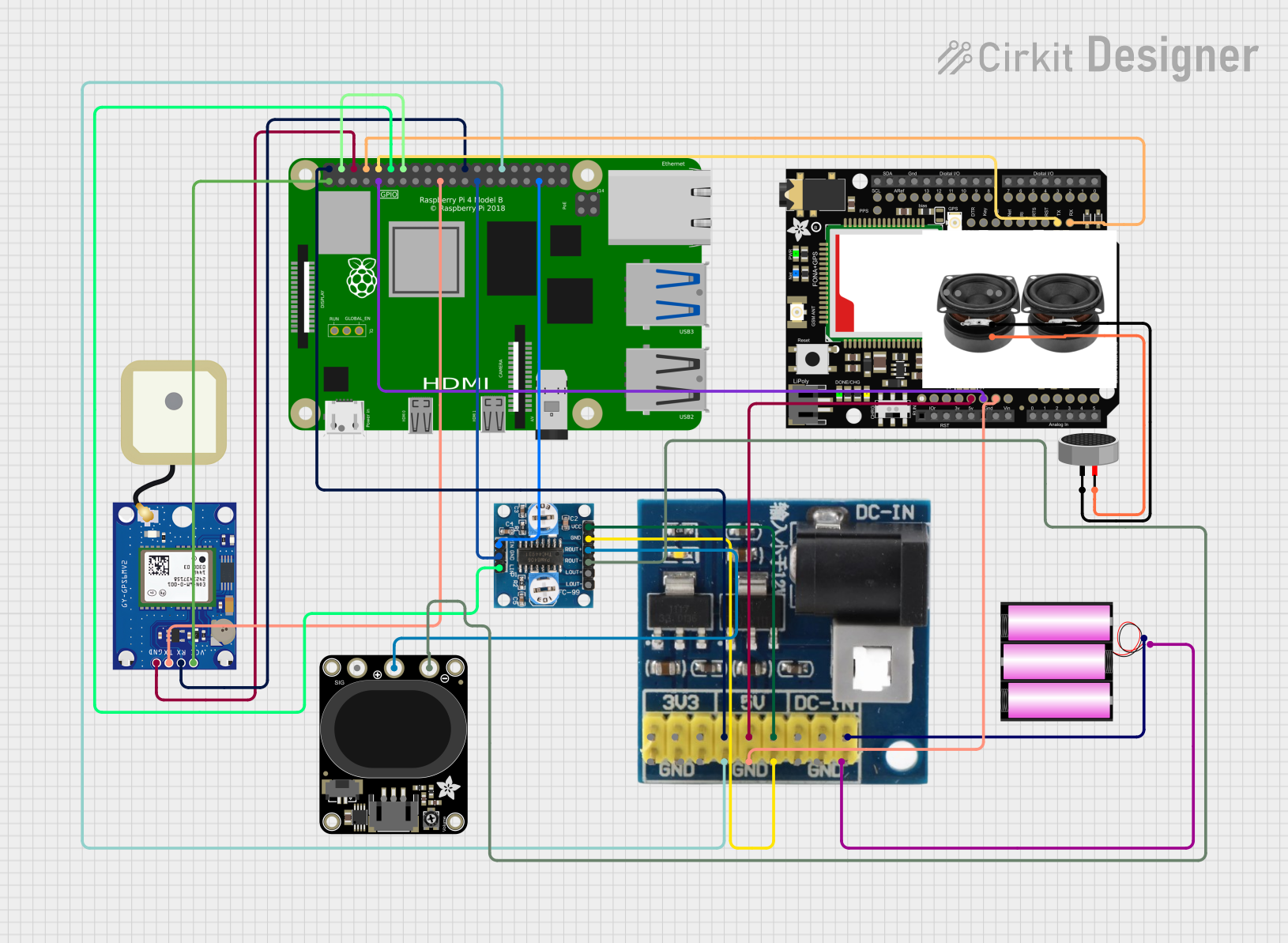
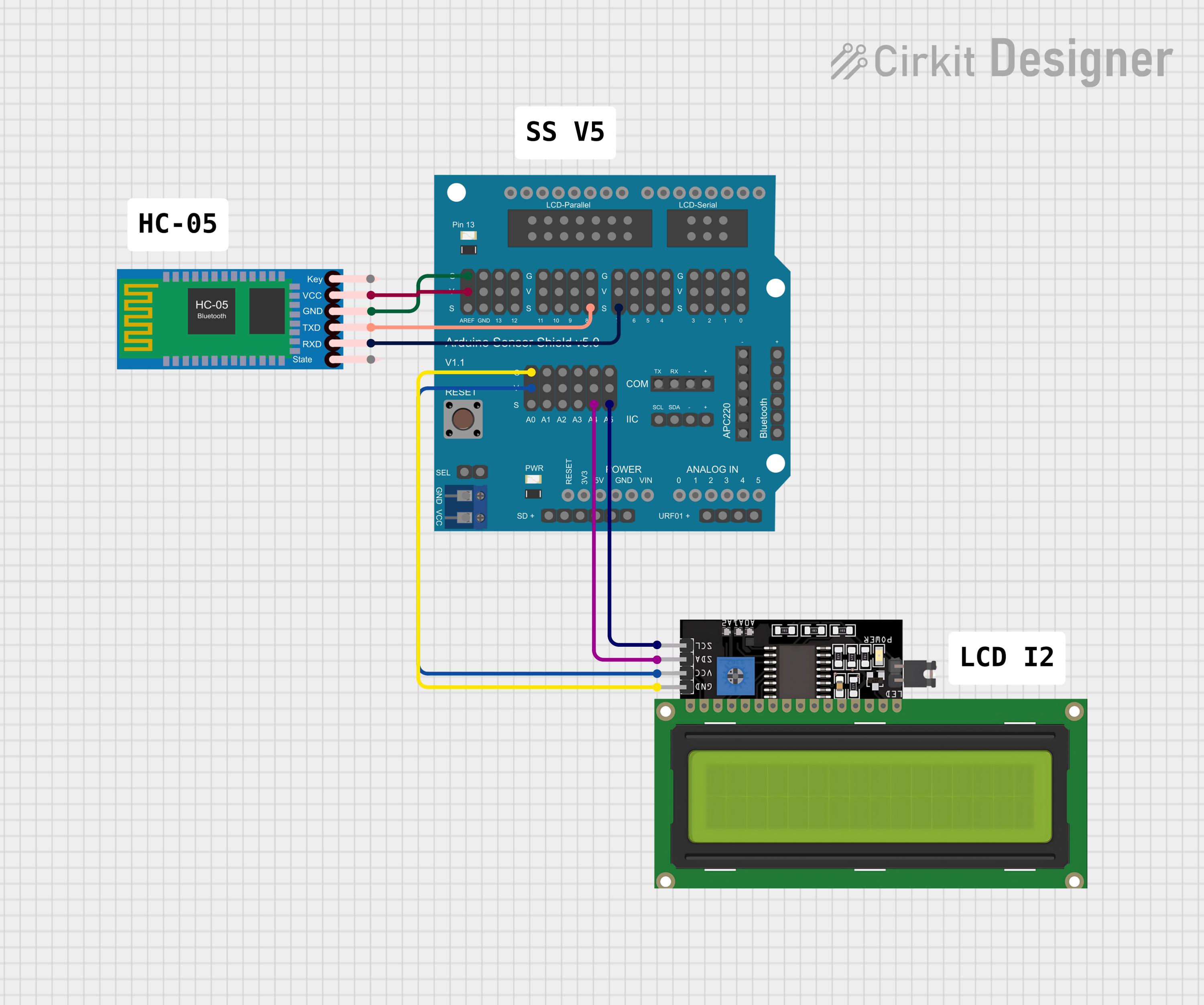
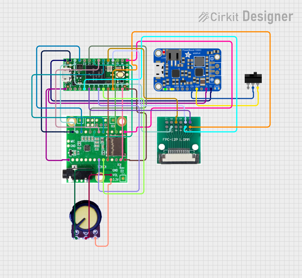
Explore Projects Built with Adafruit FONA 800 Shield
Common Applications and Use Cases
- Remote data logging and telemetry
- SMS-based remote control
- Asset tracking and geolocation
- Emergency communication systems
- IoT devices requiring cellular connectivity
Technical Specifications
Key Technical Details
- Network Support: Quad-band 850/900/1800/1900MHz - works on GSM networks worldwide.
- Voltage Requirements: 3.4-4.4VDC logic level (5V safe).
- Current Consumption: 250mA average during transmission.
- Onboard Regulator: 3.3V 800mA regulator.
- Antenna Connector: SMA connector for external antenna.
- SIM Card Slot: Standard 2FF SIM slot.
Pin Configuration and Descriptions
| Pin Number | Function | Description |
|---|---|---|
| 1 | Vio | Power supply for logic level (3.3V to 5V) |
| 2 | GND | Ground |
| 3 | Key | Active low to turn on the module |
| 4 | PS | Power status indicator |
| 5 | Reset | Active low to reset the module |
| 6 | RX | UART receive pin |
| 7 | TX | UART transmit pin |
| 8 | RI | Ring indicator, active low when incoming call |
| 9 | Netlight | Network status indicator |
| 10 | Speaker+ | Positive terminal for external speaker |
| 11 | Speaker- | Negative terminal for external speaker |
| 12 | Microphone+ | Positive terminal for external microphone |
| 13 | Microphone- | Negative terminal for external microphone |
Usage Instructions
How to Use the Component in a Circuit
- Powering the Shield: Connect the Vio pin to a 3.3V or 5V power supply from your microcontroller.
- Ground Connection: Connect the GND pin to the ground of your microcontroller.
- UART Communication: Connect the RX and TX pins to the corresponding TX and RX pins on your microcontroller.
- Antenna: Attach an appropriate GSM antenna to the SMA connector.
- SIM Card: Insert an activated GSM SIM card into the SIM card slot.
Important Considerations and Best Practices
- Ensure that the power supply can handle the peak current requirements during transmission.
- Use a level shifter if your microcontroller operates at a logic level different from 3.3V or 5V.
- Place the antenna in a position where it is not obstructed by metal objects to ensure good signal reception.
- Always power down the shield before inserting or removing the SIM card to prevent damage.
Example Code for Arduino UNO
#include <SoftwareSerial.h>

SoftwareSerial fonaSerial(2, 3); // RX, TX
// Use pin 2 to communicate with the FONA

void setup() {
  fonaSerial.begin(4800); // Set the baud rate for the FONA
  Serial.begin(115200);   // Set the baud rate for Serial monitor
  Serial.println(F("FONA basic test"));
  Serial.println(F("Initializing....(May take a few seconds)"));

  // Make sure the FONA is turned on. It should be an active low signal.
  pinMode(4, OUTPUT);
  digitalWrite(4, LOW);
  delay(1000);
  digitalWrite(4, HIGH);
}

void loop() {
  // Check for any incoming calls
  if (fonaSerial.available()) {
    Serial.write(fonaSerial.read());
  }

  // Send any characters from the Serial Monitor to the FONA
  if (Serial.available()) {
    fonaSerial.write(Serial.read());
  }
}
Troubleshooting and FAQs
Common Issues Users Might Face
- No Network Connection: Ensure the antenna is properly connected and the SIM card is activated and has network coverage.
- Power Issues: If the module does not power on, check the power supply and connections.
- Serial Communication Errors: Verify that the baud rate of the FONA and the microcontroller's serial port match.
Solutions and Tips for Troubleshooting
- Power Cycling: If the module is unresponsive, try power cycling by turning it off and on again.
- Antenna Placement: Move the antenna to a different location to avoid interference and improve signal strength.
- SIM Card Activation: Confirm that the SIM card is activated with the carrier and has the correct APN settings for data transmission.
FAQs
Q: Can I use the FONA 800 Shield with a 3.3V microcontroller?
- A: Yes, the shield is 3.3V logic level compatible, but ensure that the power supply can provide sufficient current.
Q: How do I know if the FONA 800 Shield is connected to the network?
- A: The Netlight pin will blink at different rates to indicate the network status.
Q: What should I do if I can't send or receive SMS?
- A: Check the SIM card for proper insertion, activation, and SMS plan availability. Also, ensure the antenna has a strong signal.
This documentation provides a comprehensive guide to using the Adafruit FONA 800 Shield with your Arduino projects. For further assistance, consult the Adafruit forums and support channels.