How to Use Slamtec RPLIDAR C1 : Examples, Pinouts, and Specs
Introduction
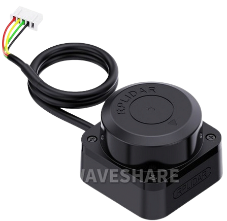
The Slamtec RPLIDAR C1 is a high-performance 360-degree laser scanner designed for mapping, navigation, and obstacle detection. It provides accurate distance measurements and environmental data, making it an essential component for robotics, automation, and other applications requiring spatial awareness. The RPLIDAR C1 is compact, lightweight, and capable of delivering real-time data, making it ideal for use in autonomous vehicles, drones, and smart home devices.
Explore Projects Built with Slamtec RPLIDAR C1
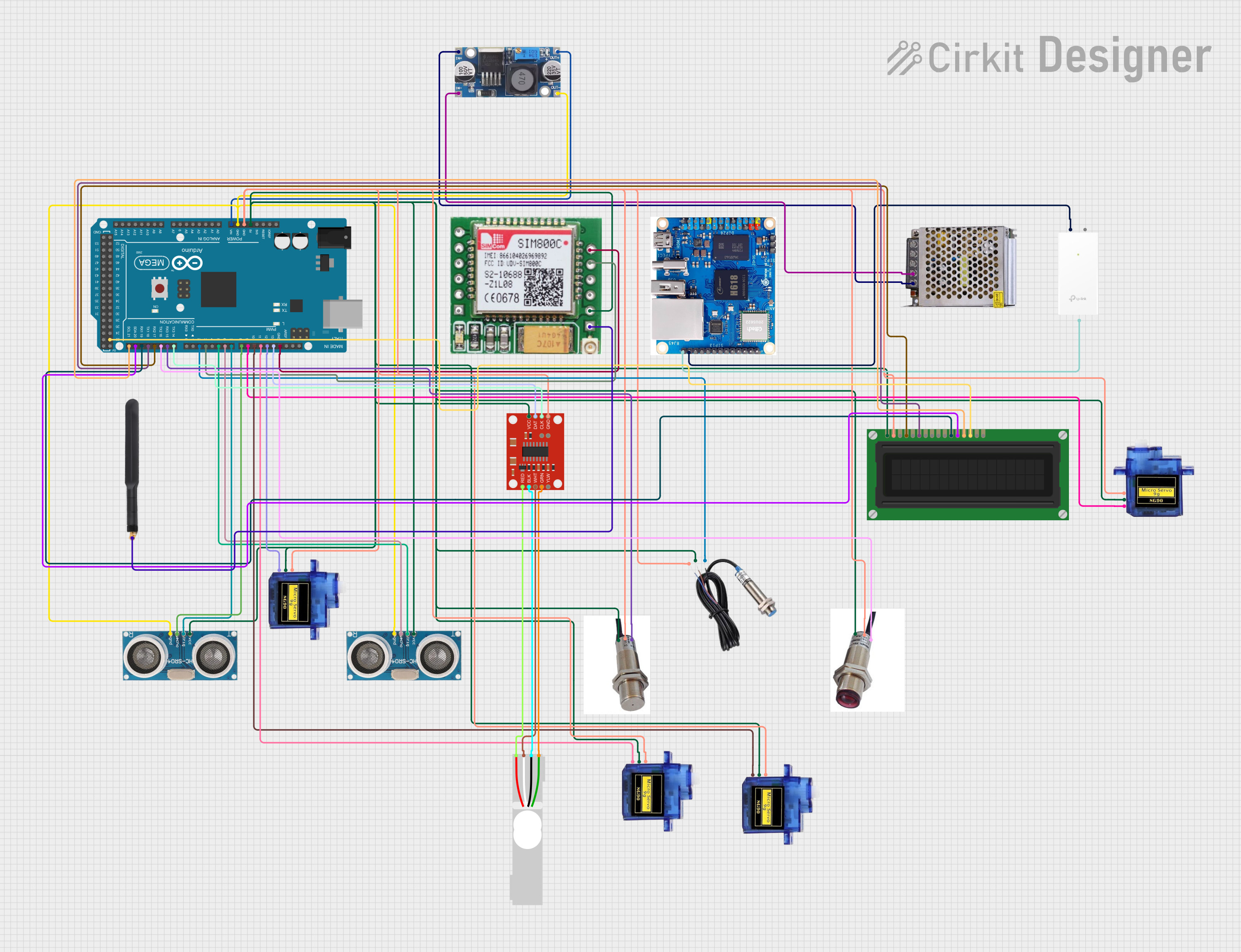
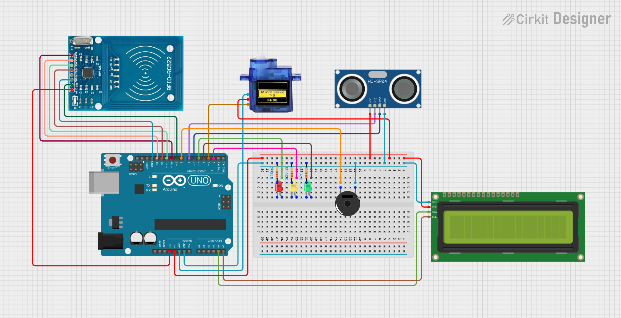
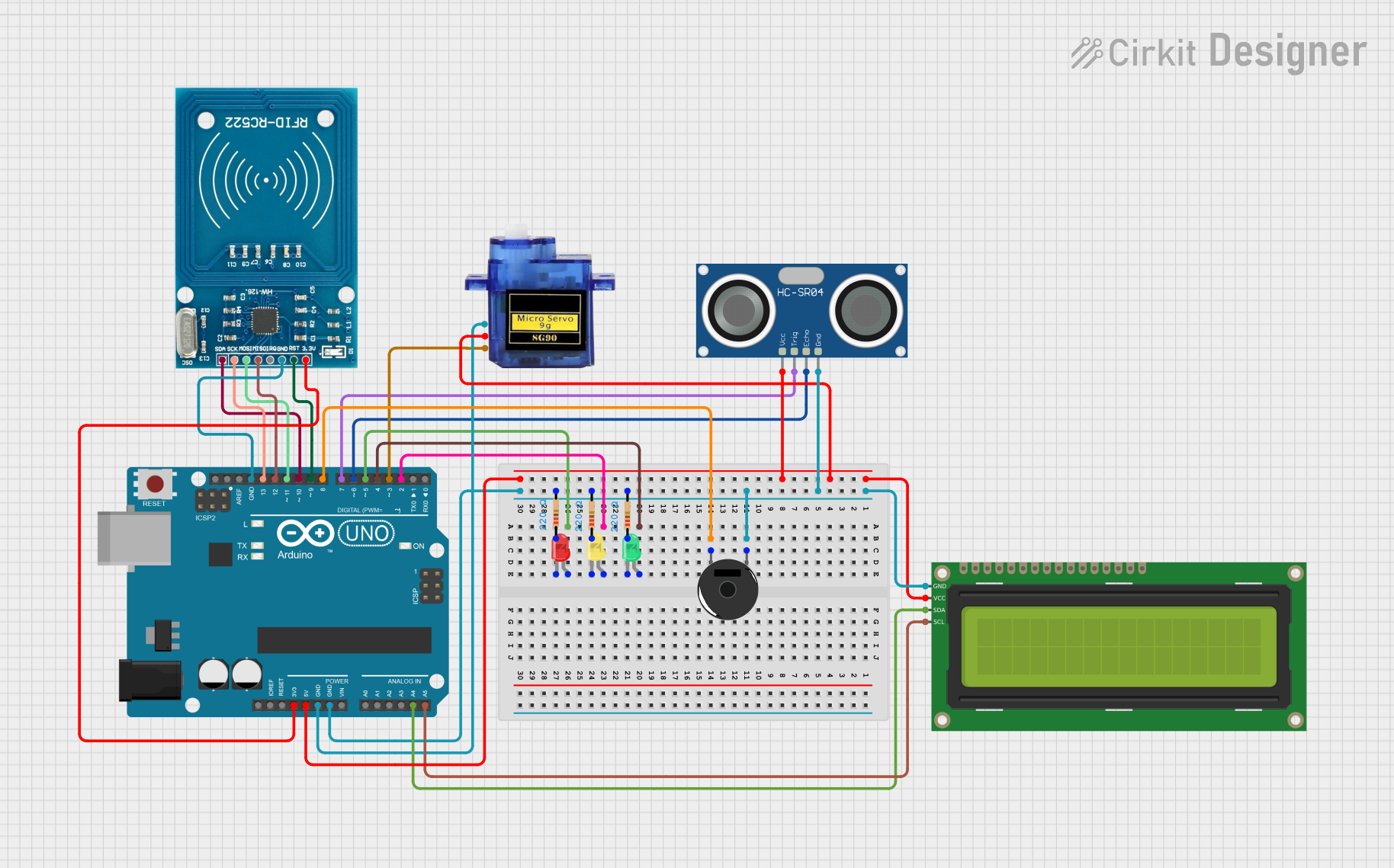

Explore Projects Built with Slamtec RPLIDAR C1
Common Applications
- Autonomous robots and vehicles for navigation and obstacle avoidance
- Indoor mapping and 3D modeling
- Smart home automation systems
- Industrial automation and safety systems
- Research and development in robotics and AI
Technical Specifications
The following table outlines the key technical specifications of the Slamtec RPLIDAR C1:
| Parameter | Value |
|---|---|
| Manufacturer | Slamtec |
| Part ID | RPLIDAR C1 |
| Scanning Range | 0.15 m to 12 m |
| Scanning Angle | 360 degrees |
| Angular Resolution | 1° to 2° |
| Distance Resolution | < 1% of the distance |
| Scanning Frequency | 5 Hz to 10 Hz |
| Communication Interface | UART (3.3V TTL) |
| Input Voltage | 5 V DC |
| Power Consumption | < 2.5 W |
| Dimensions | 70 mm (diameter) x 41 mm (height) |
| Weight | 190 g |
Pin Configuration and Descriptions
The RPLIDAR C1 uses a 5-pin interface for power and communication. The pin configuration is as follows:
| Pin Number | Pin Name | Description |
|---|---|---|
| 1 | VCC | Power input (5 V DC) |
| 2 | GND | Ground |
| 3 | TX | UART Transmit (3.3V TTL) |
| 4 | RX | UART Receive (3.3V TTL) |
| 5 | MOTOCTL | Motor control signal (PWM input for speed control) |
Usage Instructions
Connecting the RPLIDAR C1
- Power Supply: Connect the VCC pin to a 5V DC power source and the GND pin to ground.
- Communication: Use the TX and RX pins to establish a UART connection with your microcontroller or computer. Ensure the UART voltage level is 3.3V TTL.
- Motor Control: Use the MOTOCTL pin to control the motor speed via a PWM signal. If no external control is required, the motor will operate at its default speed.
Using the RPLIDAR C1 with an Arduino UNO
To interface the RPLIDAR C1 with an Arduino UNO, follow these steps:
- Connect the RPLIDAR C1's VCC and GND pins to the Arduino's 5V and GND pins, respectively.
- Connect the TX pin of the RPLIDAR C1 to the RX pin of the Arduino (pin 0).
- Connect the RX pin of the RPLIDAR C1 to the TX pin of the Arduino (pin 1).
- Use a PWM-capable pin on the Arduino to control the MOTOCTL pin if motor speed adjustment is required.
Below is an example Arduino sketch to read data from the RPLIDAR C1:
#include <SoftwareSerial.h>

// Define RX and TX pins for SoftwareSerial
SoftwareSerial lidarSerial(10, 11); // RX = pin 10, TX = pin 11

void setup() {
  Serial.begin(9600); // Initialize Serial Monitor
  lidarSerial.begin(115200); // Initialize RPLIDAR communication

  Serial.println("RPLIDAR C1 Initialized");
}

void loop() {
  if (lidarSerial.available()) {
    // Read data from RPLIDAR and send it to Serial Monitor
    char data = lidarSerial.read();
    Serial.print(data);
  }
}
Important Considerations
- Power Supply: Ensure a stable 5V power source to avoid performance issues.
- UART Voltage Levels: The RPLIDAR C1 operates at 3.3V TTL logic. Use a level shifter if your microcontroller operates at 5V logic.
- Motor Control: If motor speed control is not required, leave the MOTOCTL pin unconnected.
- Environment: Avoid using the RPLIDAR C1 in environments with excessive dust, smoke, or reflective surfaces, as these can affect measurement accuracy.
Troubleshooting and FAQs
Common Issues and Solutions
No Data Output:
- Ensure the RPLIDAR C1 is powered correctly (5V DC).
- Verify the UART connections (TX and RX) and baud rate (115200 bps).
- Check for loose or damaged wires.
Inaccurate Measurements:
- Clean the RPLIDAR's lens to remove dust or smudges.
- Avoid reflective or transparent surfaces in the scanning area.
Motor Not Spinning:
- Check the MOTOCTL pin connection and ensure a proper PWM signal is provided.
- Verify the power supply voltage and current capacity.
Interference with Other Devices:
- Ensure the RPLIDAR C1 is not placed near devices emitting strong electromagnetic interference.
- Use shielded cables for UART communication.
FAQs
Q: Can the RPLIDAR C1 be used outdoors?
A: The RPLIDAR C1 is primarily designed for indoor use. Outdoor use may result in reduced accuracy due to environmental factors like sunlight and weather conditions.
Q: What is the maximum range of the RPLIDAR C1?
A: The maximum scanning range is 12 meters under optimal conditions.
Q: Can I use the RPLIDAR C1 with a Raspberry Pi?
A: Yes, the RPLIDAR C1 can be connected to a Raspberry Pi via its UART interface. Use a USB-to-UART adapter if needed.
Q: How do I clean the RPLIDAR C1?
A: Use a soft, lint-free cloth to gently clean the lens. Avoid using abrasive materials or liquids.
By following this documentation, users can effectively integrate and operate the Slamtec RPLIDAR C1 in their projects.