How to Use MLX90393: Examples, Pinouts, and Specs
Introduction
The MLX90393, manufactured by Melexis, is a highly versatile 3D magnetic sensor capable of measuring magnetic fields in three dimensions (X, Y, Z). It is designed for applications requiring precise position sensing, navigation, and robotics. With its high accuracy, low power consumption, and I²C/SPI communication interface, the MLX90393 is ideal for use in portable devices, industrial automation, and automotive systems.
Explore Projects Built with MLX90393


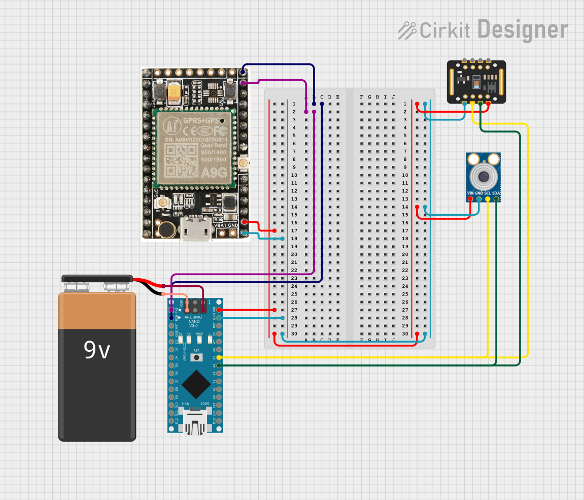
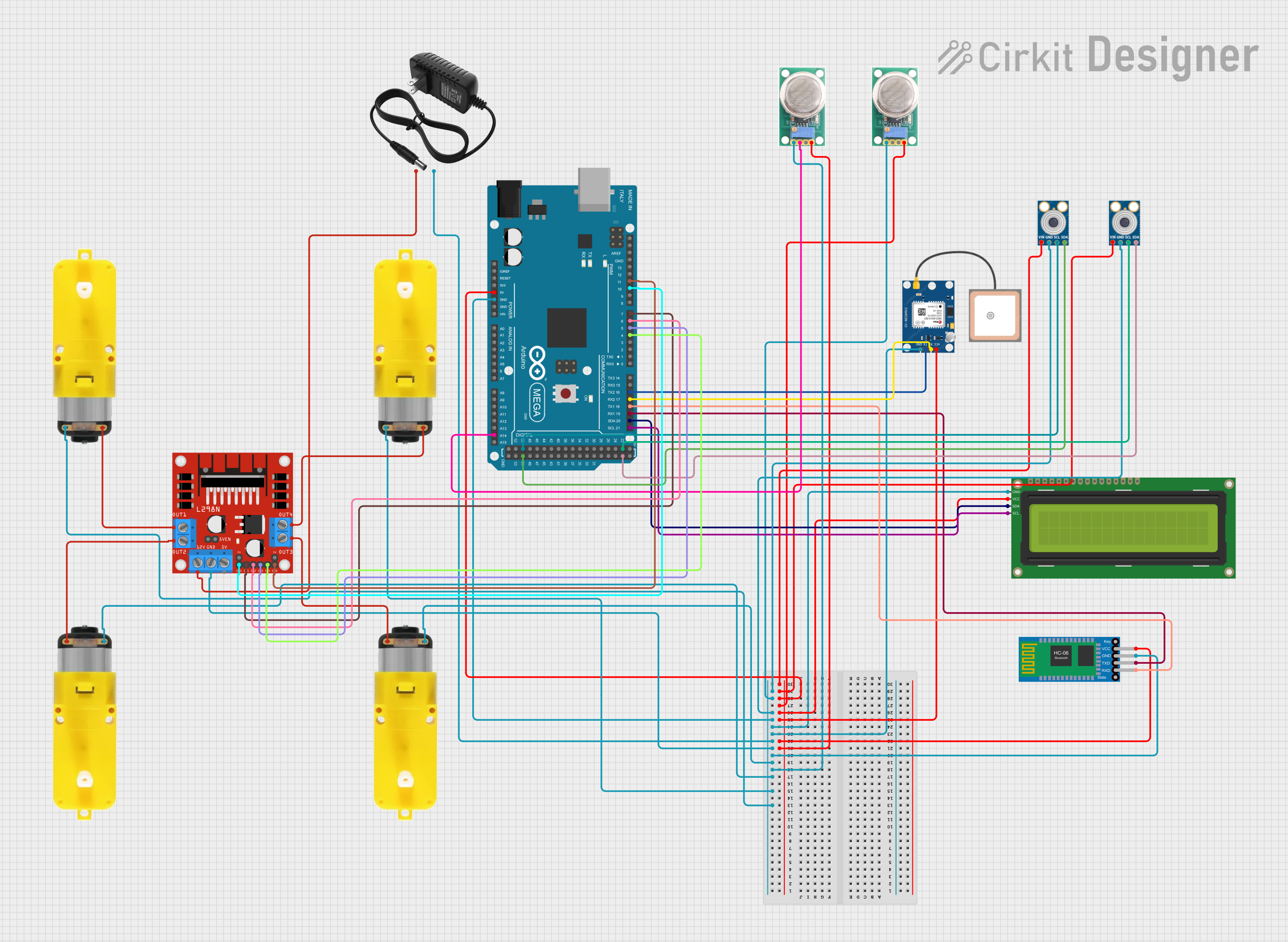
Explore Projects Built with MLX90393
Common Applications
- Position sensing in joysticks, knobs, and rotary encoders
- Navigation systems, including compasses and GPS augmentation
- Robotics for motion tracking and control
- Industrial automation for proximity and alignment detection
- Consumer electronics, such as wearables and gaming devices
Technical Specifications
Key Technical Details
| Parameter | Value |
|---|---|
| Supply Voltage (VDD) | 2.2V to 3.6V |
| Operating Current | 5 µA (low-power mode), 1.8 mA (active) |
| Magnetic Field Range | ±50 mT to ±200 mT (configurable) |
| Communication Interface | I²C or SPI |
| Resolution | 16-bit |
| Operating Temperature | -40°C to +85°C |
| Package | 3x3 mm QFN-16 |
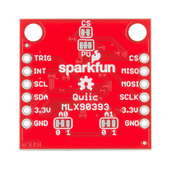
Pin Configuration and Descriptions
| Pin Number | Pin Name | Description |
|---|---|---|
| 1 | VDD | Power supply (2.2V to 3.6V) |
| 2 | GND | Ground |
| 3 | SCL/SPC | I²C clock line / SPI clock |
| 4 | SDA/SDI | I²C data line / SPI data input |
| 5 | SDO | SPI data output (leave unconnected for I²C) |
| 6 | CS | Chip select for SPI (tie to VDD for I²C) |
| 7-16 | NC | Not connected (leave floating) |
Usage Instructions
How to Use the MLX90393 in a Circuit
- Power Supply: Connect the VDD pin to a 2.2V-3.6V power source and the GND pin to ground.
- Communication Interface:
- For I²C: Connect the SCL and SDA pins to the corresponding I²C lines of your microcontroller. Use pull-up resistors (typically 4.7 kΩ) on both lines.
- For SPI: Connect the SPC, SDI, SDO, and CS pins to the corresponding SPI lines of your microcontroller.
- Bypass Capacitor: Place a 100 nF capacitor close to the VDD pin for power supply decoupling.
- Magnetic Field Measurement:
- Configure the sensor's resolution, gain, and magnetic field range via the communication interface.
- Read the X, Y, and Z magnetic field data from the sensor registers.
Important Considerations and Best Practices
- I²C Address: The default I²C address of the MLX90393 is
0x0C. Ensure no address conflicts if multiple devices are on the same bus. - Magnetic Interference: Avoid placing the sensor near strong magnetic sources to prevent measurement errors.
- Temperature Compensation: The sensor includes built-in temperature compensation for improved accuracy.
- Low-Power Mode: Use the low-power mode for battery-operated applications to minimize current consumption.
Example Code for Arduino UNO (I²C)
#include <Wire.h>

// MLX90393 I²C address
#define MLX90393_ADDR 0x0C

void setup() {
  Wire.begin(); // Initialize I²C communication
  Serial.begin(9600); // Initialize serial communication for debugging

  // Send a reset command to the MLX90393
  Wire.beginTransmission(MLX90393_ADDR);
  Wire.write(0x80); // Command to reset the sensor
  Wire.endTransmission();
  delay(10); // Wait for the sensor to reset

  Serial.println("MLX90393 initialized.");
}

void loop() {
  // Request magnetic field data from the sensor
  Wire.beginTransmission(MLX90393_ADDR);
  Wire.write(0x3E); // Command to read measurement data
  Wire.endTransmission();

  // Read the response (6 bytes: X, Y, Z data)
  Wire.requestFrom(MLX90393_ADDR, 6);
  if (Wire.available() == 6) {
    int16_t x = (Wire.read() << 8) | Wire.read(); // Combine MSB and LSB for X
    int16_t y = (Wire.read() << 8) | Wire.read(); // Combine MSB and LSB for Y
    int16_t z = (Wire.read() << 8) | Wire.read(); // Combine MSB and LSB for Z

    // Print the magnetic field data
    Serial.print("X: "); Serial.print(x);
    Serial.print(" Y: "); Serial.print(y);
    Serial.print(" Z: "); Serial.println(z);
  }

  delay(500); // Wait before the next reading
}
Troubleshooting and FAQs
Common Issues and Solutions
No Response from the Sensor:
- Ensure the correct I²C address (
0x0C) is used. - Check the wiring, especially the pull-up resistors on the I²C lines.
- Verify the power supply voltage is within the specified range (2.2V to 3.6V).
- Ensure the correct I²C address (
Incorrect Magnetic Field Readings:
- Ensure the sensor is not exposed to strong magnetic interference.
- Verify the configuration settings (resolution, gain, and range) are appropriate for your application.
Communication Errors:
- Check the clock speed of the I²C or SPI bus. The MLX90393 supports up to 1 MHz for I²C and 10 MHz for SPI.
- Ensure proper grounding and minimize noise on the communication lines.
FAQs
Can the MLX90393 measure static magnetic fields? Yes, the sensor can measure both static and dynamic magnetic fields.
What is the maximum distance for accurate magnetic field sensing? The effective sensing range depends on the strength of the magnetic source and the sensor's configuration. For weak fields, the sensor should be placed closer to the source.
Can I use multiple MLX90393 sensors on the same I²C bus? Yes, but each sensor must have a unique I²C address. This can be configured using the ADDR pin or software commands.
Is the MLX90393 suitable for outdoor use? The sensor operates within a temperature range of -40°C to +85°C, making it suitable for many outdoor applications. However, additional protection may be required against moisture and dust.