Cirkit Designer Logo
Cirkit Designer
Your all-in-one circuit design IDE
Home / 
Component Documentation

How to Use LM2596: Examples, Pinouts, and Specs

Image of LM2596
Cirkit Designer LogoDesign with LM2596 in Cirkit Designer

Introduction

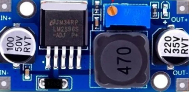
The LM2596 is a highly efficient, step-down voltage regulator that is capable of driving a 3A load with excellent line and load regulation. This switch-mode power supply (SMPS) component is widely used in a variety of applications, including but not limited to, consumer electronics, embedded systems, and industrial equipment. Its ability to convert a higher input voltage into a lower output voltage makes it ideal for creating stable power supplies in electronic projects.

Explore Projects Built with LM2596

Use Cirkit Designer to design, explore, and prototype these projects online. Some projects support real-time simulation. Click "Open Project" to start designing instantly!
ESP32-Based Solar-Powered Current Monitoring System with OLED Display
Image of Solar Tracker and Monitoring System: A project utilizing LM2596 in a practical application
This circuit features an ESP32 microcontroller interfaced with a 0.96" OLED display, multiple LDR sensors with voltage dividers, an ACS712 current sensor, and two servomotors. The ESP32 reads analog values from the LDRs and the current sensor, and controls the servomotors. The LM2596 module steps down voltage for the circuit, which is powered by a combination of a solar panel and a 12V battery, with the current sensor monitoring the load current.
Cirkit Designer LogoOpen Project in Cirkit Designer
Arduino Nano Based GPS Tracker with GSM Communication and Accelerometer
Image of Circuit Aayush: A project utilizing LM2596 in a practical application
This circuit is designed for communication and location tracking purposes. It features an Arduino Nano interfaced with a SIM800L GSM module for cellular connectivity, a GPS NEO 6M module for obtaining geographical coordinates, and an AITrip ADXL335 GY-61 accelerometer for motion sensing. The LM2596 Step Down Module is used to regulate the power supply to the components.
Cirkit Designer LogoOpen Project in Cirkit Designer
Arduino GSM Security System with Motion Detection and Light Sensing
Image of Smart Home Security: A project utilizing LM2596 in a practical application
This circuit is designed to interface an Arduino UNO with a SIM800L GSM module, PIR sensor, photocell, buzzer, and multiple LEDs. It is likely intended for environmental monitoring and alerting, with the capability to communicate over GSM for remote notifications. The LM2596 module provides voltage regulation for the GSM module.
Cirkit Designer LogoOpen Project in Cirkit Designer
ESP8266 and SIM800L Based GPS Tracker with I2C LCD Display and Battery Power
Image of Little Innovator Competition: A project utilizing LM2596 in a practical application
This circuit integrates an ESP8266 NodeMCU microcontroller with a SIM800L GSM module, a GPS NEO 6M module, and a 16x2 I2C LCD display for communication and location tracking. It also includes a pushbutton for user input, a piezo buzzer for audio alerts, and is powered by a 2x 18650 battery pack through an LM2596 step-down module.
Cirkit Designer LogoOpen Project in Cirkit Designer

Explore Projects Built with LM2596

Use Cirkit Designer to design, explore, and prototype these projects online. Some projects support real-time simulation. Click "Open Project" to start designing instantly!
Image of Solar Tracker and Monitoring System: A project utilizing LM2596 in a practical application
ESP32-Based Solar-Powered Current Monitoring System with OLED Display
This circuit features an ESP32 microcontroller interfaced with a 0.96" OLED display, multiple LDR sensors with voltage dividers, an ACS712 current sensor, and two servomotors. The ESP32 reads analog values from the LDRs and the current sensor, and controls the servomotors. The LM2596 module steps down voltage for the circuit, which is powered by a combination of a solar panel and a 12V battery, with the current sensor monitoring the load current.
Cirkit Designer LogoOpen Project in Cirkit Designer
Image of Circuit Aayush: A project utilizing LM2596 in a practical application
Arduino Nano Based GPS Tracker with GSM Communication and Accelerometer
This circuit is designed for communication and location tracking purposes. It features an Arduino Nano interfaced with a SIM800L GSM module for cellular connectivity, a GPS NEO 6M module for obtaining geographical coordinates, and an AITrip ADXL335 GY-61 accelerometer for motion sensing. The LM2596 Step Down Module is used to regulate the power supply to the components.
Cirkit Designer LogoOpen Project in Cirkit Designer
Image of Smart Home Security: A project utilizing LM2596 in a practical application
Arduino GSM Security System with Motion Detection and Light Sensing
This circuit is designed to interface an Arduino UNO with a SIM800L GSM module, PIR sensor, photocell, buzzer, and multiple LEDs. It is likely intended for environmental monitoring and alerting, with the capability to communicate over GSM for remote notifications. The LM2596 module provides voltage regulation for the GSM module.
Cirkit Designer LogoOpen Project in Cirkit Designer
Image of Little Innovator Competition: A project utilizing LM2596 in a practical application
ESP8266 and SIM800L Based GPS Tracker with I2C LCD Display and Battery Power
This circuit integrates an ESP8266 NodeMCU microcontroller with a SIM800L GSM module, a GPS NEO 6M module, and a 16x2 I2C LCD display for communication and location tracking. It also includes a pushbutton for user input, a piezo buzzer for audio alerts, and is powered by a 2x 18650 battery pack through an LM2596 step-down module.
Cirkit Designer LogoOpen Project in Cirkit Designer

Common Applications and Use Cases

  • Power supplies for battery-operated devices
  • Automotive electronics
  • Portable electronics
  • Voltage regulation for microcontrollers and other digital devices
  • Step-down modules for embedded systems

Technical Specifications

Key Technical Details

  • Output Voltage: Adjustable from 1.23V to 37V
  • Input Voltage: 4.5V to 40V
  • Output Current: 3A (maximum)
  • Switching Frequency: 150 kHz (typical)
  • Efficiency: Up to 92% (depends on input and output voltage)
  • Operating Temperature: -40°C to +125°C

Pin Configuration and Descriptions

Pin Number Name Description
1 Vin Input voltage (4.5V to 40V)
2 Output Regulated output voltage
3 Ground Common ground for input and output
4 Feedback (FB) Feedback pin for output voltage regulation
5 On/Off Enables or disables the regulator output

Usage Instructions

How to Use the Component in a Circuit

  1. Connect the input voltage (4.5V to 40V) to the Vin pin.
  2. Connect the ground from your power source to the Ground pin.
  3. The Output pin provides the regulated voltage, which can be adjusted using a resistor divider connected to the Feedback pin.
  4. The On/Off pin can be left open for normal operation or driven low to turn off the output.

Important Considerations and Best Practices

  • Always use capacitors on the input and output as recommended in the datasheet to minimize voltage ripple and noise.
  • Ensure that the maximum input voltage does not exceed 40V and the output current does not surpass 3A.
  • Use a heat sink if the regulator is expected to dissipate significant power.
  • Place the LM2596 close to the power source and load to reduce losses in the PCB traces.
  • Avoid running the regulator at its maximum ratings continuously; leave some margin for reliability.

Example Circuit and Arduino Code

The following example demonstrates how to use the LM2596 to power an Arduino UNO, which requires a regulated 5V supply.

// There is no specific code required for the LM2596 as it is a hardware component.
// However, the following is an example of how you might set up an Arduino to monitor
// the output voltage of the LM2596 using an analog input.

const int analogPin = A0; // Connect the LM2596 output to Arduino analog pin A0

void setup() {
  Serial.begin(9600);
}

void loop() {
  int sensorValue = analogRead(analogPin); // Read the analog value (0 to 1023)
  float voltage = sensorValue * (5.0 / 1023.0); // Convert to voltage
  Serial.print("Output Voltage: ");
  Serial.print(voltage);
  Serial.println(" V");
  delay(1000); // Wait for a second before reading again
}

Troubleshooting and FAQs

Common Issues Users Might Face

  • Output voltage is too high or too low: Check the resistor divider connected to the Feedback pin and ensure it is configured correctly.
  • Regulator is overheating: Ensure adequate heat sinking and airflow. Check if the input voltage is too high or if the output current is exceeding the recommended limits.
  • Output voltage is unstable: Verify that the input and output capacitors are of the correct value and are placed as close to the regulator as possible.

Solutions and Tips for Troubleshooting

  • Always start by checking connections and ensuring that the input voltage is within the specified range.
  • Measure the output voltage and adjust the feedback resistors as necessary to achieve the desired output.
  • If the device is not turning on, check the On/Off pin to ensure it is not being inadvertently driven low.

FAQs

Q: Can I get a fixed output voltage from the LM2596? A: Yes, the LM2596 is available in versions with fixed output voltages, such as 5V, 12V, etc.

Q: What is the purpose of the On/Off pin? A: The On/Off pin allows you to shut down the regulator, reducing the quiescent current to a minimum when the output is not needed.

Q: How do I choose the right inductor and capacitors for my application? A: Refer to the LM2596 datasheet for recommended inductor and capacitor values based on your specific input and output voltage requirements.