Cirkit Designer Logo
Cirkit Designer
Your all-in-one circuit design IDE
Home / 
Component Documentation

How to Use BMM350_I2C: Examples, Pinouts, and Specs

Image of BMM350_I2C
Cirkit Designer LogoDesign with BMM350_I2C in Cirkit Designer

Introduction

The BMM350_I2C is a high-performance 3-axis digital magnetometer manufactured by Bosch. Designed for precision and reliability, this component measures magnetic fields along the X, Y, and Z axes, making it ideal for applications requiring accurate navigation, orientation, and heading detection. Its I2C communication interface ensures seamless integration with microcontrollers and other digital systems.

Explore Projects Built with BMM350_I2C

Use Cirkit Designer to design, explore, and prototype these projects online. Some projects support real-time simulation. Click "Open Project" to start designing instantly!
Arduino Mega 2560 and Adafruit BNO085 IMU Sensor Integration
Image of bno085: A project utilizing BMM350_I2C in a practical application
This circuit connects an Adafruit BNO085 9-DOF Orientation IMU Fusion sensor to an Arduino Mega 2560 microcontroller. The sensor's power (3.3V and GND) and I2C communication lines (SCL and SDA) are interfaced with corresponding pins on the Arduino, enabling the microcontroller to receive orientation and motion data from the sensor. The provided code template is a basic Arduino sketch structure without specific functionality implemented for the sensor.
Cirkit Designer LogoOpen Project in Cirkit Designer
Raspberry Pi 4B Multi-Sensor Data Acquisition System
Image of project: A project utilizing BMM350_I2C in a practical application
This circuit integrates multiple sensors, including an accelerometer (ADXL345), a barometric pressure sensor (BMP180), a pulse oximeter (max30100), and an infrared temperature sensor (mlx90614), all interfaced with a Raspberry Pi 4B via I2C communication. The Raspberry Pi serves as the central processing unit, collecting and processing data from the sensors for various applications such as health monitoring and environmental sensing.
Cirkit Designer LogoOpen Project in Cirkit Designer
Arduino Mega 2560-Based Robotic Controller with Bluetooth and Sensor Integration
Image of KLTN2: A project utilizing BMM350_I2C in a practical application
This circuit is designed to interface with various sensors and actuators through an Arduino Mega 2560 for monitoring and control purposes. It features visual output via I2C LCD screens and RGB LEDs, distance and object detection using ultrasonic and IR sensors, motor control with an L298N driver, and wireless communication through HC-05 Bluetooth modules. The provided code is a template and does not yet implement the intended functionalities.
Cirkit Designer LogoOpen Project in Cirkit Designer
MPU-9250 and NUCLEO-F072RB Based Motion Sensing System
Image of MPU-9250 I2C: A project utilizing BMM350_I2C in a practical application
This circuit interfaces an MPU-9250/6500/9255 sensor module with a NUCLEO-F072RB microcontroller board. The sensor module is powered by the 3.3V supply from the microcontroller and communicates via the I2C protocol using the SCL and SDA lines.
Cirkit Designer LogoOpen Project in Cirkit Designer

Explore Projects Built with BMM350_I2C

Use Cirkit Designer to design, explore, and prototype these projects online. Some projects support real-time simulation. Click "Open Project" to start designing instantly!
Image of bno085: A project utilizing BMM350_I2C in a practical application
Arduino Mega 2560 and Adafruit BNO085 IMU Sensor Integration
This circuit connects an Adafruit BNO085 9-DOF Orientation IMU Fusion sensor to an Arduino Mega 2560 microcontroller. The sensor's power (3.3V and GND) and I2C communication lines (SCL and SDA) are interfaced with corresponding pins on the Arduino, enabling the microcontroller to receive orientation and motion data from the sensor. The provided code template is a basic Arduino sketch structure without specific functionality implemented for the sensor.
Cirkit Designer LogoOpen Project in Cirkit Designer
Image of project: A project utilizing BMM350_I2C in a practical application
Raspberry Pi 4B Multi-Sensor Data Acquisition System
This circuit integrates multiple sensors, including an accelerometer (ADXL345), a barometric pressure sensor (BMP180), a pulse oximeter (max30100), and an infrared temperature sensor (mlx90614), all interfaced with a Raspberry Pi 4B via I2C communication. The Raspberry Pi serves as the central processing unit, collecting and processing data from the sensors for various applications such as health monitoring and environmental sensing.
Cirkit Designer LogoOpen Project in Cirkit Designer
Image of KLTN2: A project utilizing BMM350_I2C in a practical application
Arduino Mega 2560-Based Robotic Controller with Bluetooth and Sensor Integration
This circuit is designed to interface with various sensors and actuators through an Arduino Mega 2560 for monitoring and control purposes. It features visual output via I2C LCD screens and RGB LEDs, distance and object detection using ultrasonic and IR sensors, motor control with an L298N driver, and wireless communication through HC-05 Bluetooth modules. The provided code is a template and does not yet implement the intended functionalities.
Cirkit Designer LogoOpen Project in Cirkit Designer
Image of MPU-9250 I2C: A project utilizing BMM350_I2C in a practical application
MPU-9250 and NUCLEO-F072RB Based Motion Sensing System
This circuit interfaces an MPU-9250/6500/9255 sensor module with a NUCLEO-F072RB microcontroller board. The sensor module is powered by the 3.3V supply from the microcontroller and communicates via the I2C protocol using the SCL and SDA lines.
Cirkit Designer LogoOpen Project in Cirkit Designer

Common Applications

  • Electronic compasses
  • GPS navigation systems
  • Augmented reality (AR) devices
  • Robotics and drones
  • Industrial automation
  • Wearable devices

Technical Specifications

The following table outlines the key technical details of the BMM350_I2C:

Parameter Value
Manufacturer Bosch
Part ID BMM350
Interface I2C
Operating Voltage 1.8V to 3.6V
Current Consumption 0.5 mA (typical)
Measurement Range ±1300 µT (microteslas)
Resolution 0.3 µT
Operating Temperature -40°C to +85°C
Dimensions 2.0 mm x 2.0 mm x 0.95 mm

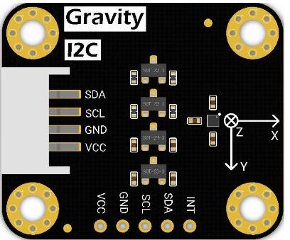
Pin Configuration and Descriptions

The BMM350_I2C has a compact package with the following pin configuration:

Pin Number Pin Name Description
1 VDD Power supply (1.8V to 3.6V)
2 GND Ground
3 SDA I2C data line
4 SCL I2C clock line
5 INT Interrupt output (optional, configurable)
6 NC Not connected (leave floating or grounded)

Usage Instructions

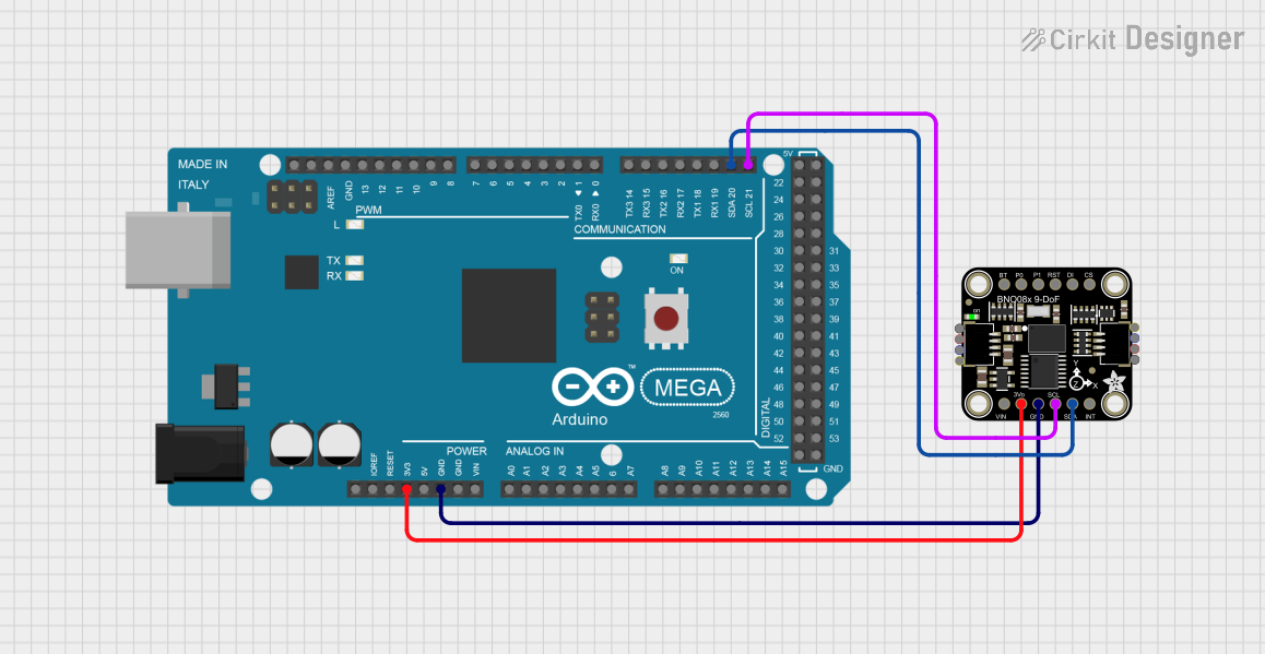
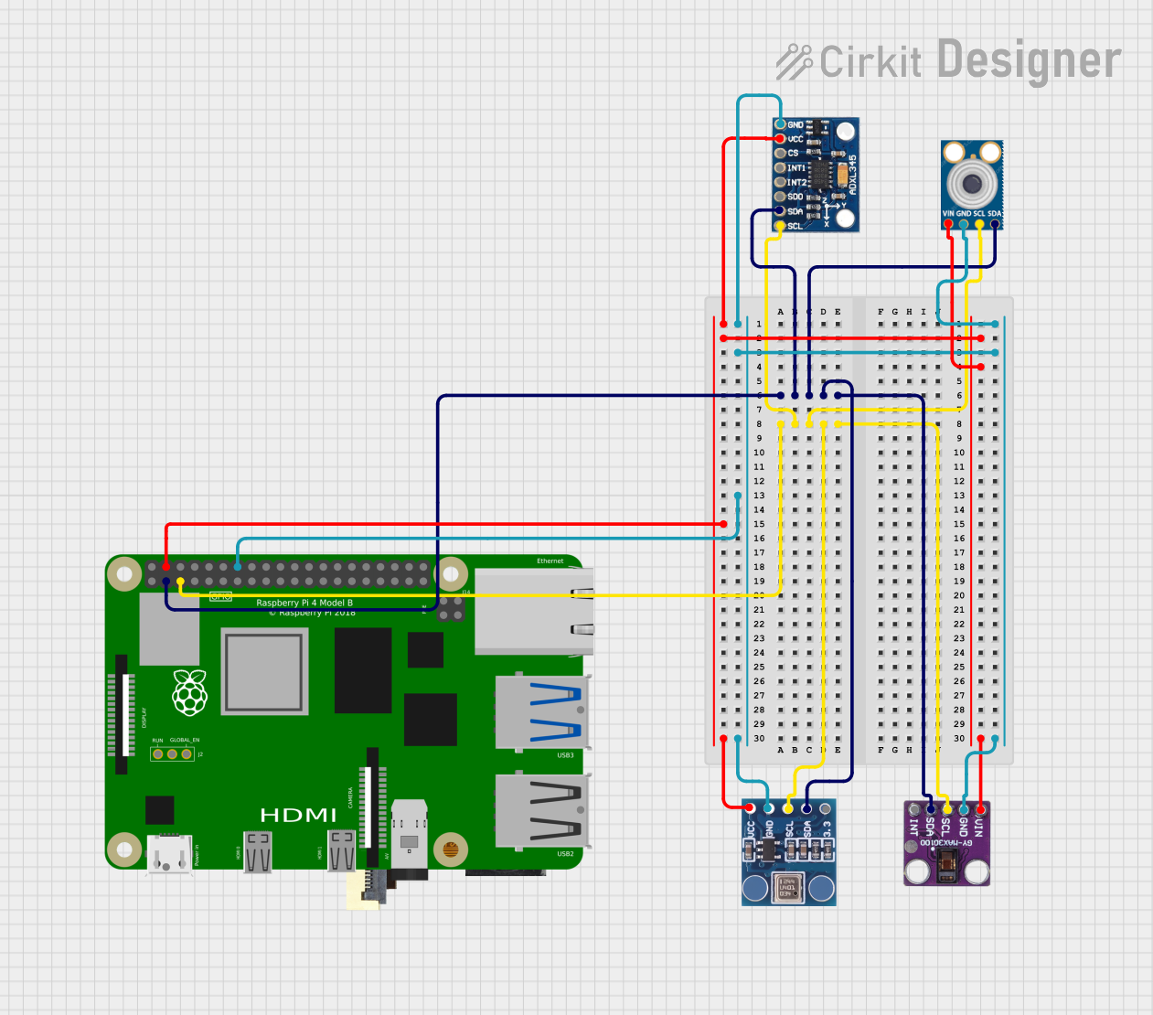
How to Use the BMM350_I2C in a Circuit

  1. Power Supply: Connect the VDD pin to a regulated power source (1.8V to 3.6V) and the GND pin to the ground.
  2. I2C Communication: Connect the SDA and SCL pins to the corresponding I2C lines of your microcontroller. Use pull-up resistors (typically 4.7 kΩ) on both lines if not already present on your board.
  3. Interrupt Pin (Optional): If using the interrupt feature, connect the INT pin to a GPIO pin on your microcontroller. Configure it as an input pin.
  4. Bypass NC Pin: Leave the NC pin unconnected or tie it to the ground.

Important Considerations

  • Ensure the I2C bus operates at a compatible voltage level with the BMM350 (1.8V to 3.6V).
  • Use decoupling capacitors (e.g., 0.1 µF) near the VDD pin to stabilize the power supply.
  • Avoid placing the magnetometer near strong magnetic sources or ferromagnetic materials to prevent interference.
  • Calibrate the sensor for your specific application to achieve optimal accuracy.

Example Code for Arduino UNO

Below is an example of how to interface the BMM350_I2C with an Arduino UNO:

#include <Wire.h> // Include the Wire library for I2C communication

#define BMM350_ADDRESS 0x10 // Default I2C address of the BMM350

void setup() {
  Wire.begin(); // Initialize I2C communication
  Serial.begin(9600); // Start serial communication for debugging

  // Initialize the BMM350
  Wire.beginTransmission(BMM350_ADDRESS);
  Wire.write(0x4B); // Example: Write to a control register (replace with actual)
  Wire.write(0x01); // Example: Set the register value (replace with actual)
  Wire.endTransmission();

  Serial.println("BMM350 Initialized");
}

void loop() {
  // Request data from the BMM350
  Wire.beginTransmission(BMM350_ADDRESS);
  Wire.write(0x42); // Example: Register address for magnetic data (replace)
  Wire.endTransmission(false);
  Wire.requestFrom(BMM350_ADDRESS, 6); // Request 6 bytes (X, Y, Z data)

  if (Wire.available() == 6) {
    int16_t magX = (Wire.read() << 8) | Wire.read(); // Combine MSB and LSB for X
    int16_t magY = (Wire.read() << 8) | Wire.read(); // Combine MSB and LSB for Y
    int16_t magZ = (Wire.read() << 8) | Wire.read(); // Combine MSB and LSB for Z

    // Print the magnetic field values
    Serial.print("Magnetic Field (µT): X=");
    Serial.print(magX);
    Serial.print(", Y=");
    Serial.print(magY);
    Serial.print(", Z=");
    Serial.println(magZ);
  }

  delay(500); // Wait for 500ms before the next reading
}

Troubleshooting and FAQs

Common Issues

  1. No Response from the Sensor

    • Ensure the I2C address (default: 0x10) matches the one in your code.
    • Check the wiring for loose or incorrect connections.
    • Verify that pull-up resistors are present on the SDA and SCL lines.
  2. Inaccurate Readings

    • Perform a calibration routine to account for environmental magnetic interference.
    • Ensure the sensor is not placed near strong magnetic fields or ferromagnetic materials.
  3. I2C Communication Errors

    • Confirm that the I2C clock speed is within the supported range (typically up to 400 kHz).
    • Check for noise or interference on the I2C lines.

FAQs

Q: Can the BMM350_I2C operate at 5V?
A: No, the BMM350_I2C operates within a voltage range of 1.8V to 3.6V. Use a level shifter if interfacing with a 5V system.

Q: How do I calibrate the BMM350?
A: Calibration involves collecting raw magnetic field data while rotating the sensor in all directions. Use this data to compute offset and scaling factors for each axis.

Q: What is the maximum measurement range of the BMM350?
A: The BMM350 can measure magnetic fields within a range of ±1300 µT.

Q: Can I use the BMM350 with SPI instead of I2C?
A: No, the BMM350_I2C is specifically designed for I2C communication. For SPI, consider other Bosch magnetometer models.