Cirkit Designer Logo
Cirkit Designer
Your all-in-one circuit design IDE
Home / 
Component Documentation

How to Use Mean Well SDR-480-48: Examples, Pinouts, and Specs

Image of Mean Well SDR-480-48
Cirkit Designer LogoDesign with Mean Well SDR-480-48 in Cirkit Designer

Introduction

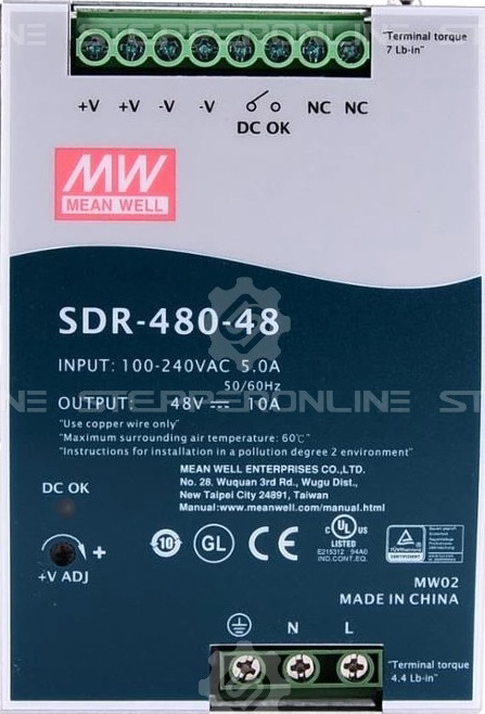
The Mean Well SDR-480-48 is a high-performance, 480W, 48V single-output switching power supply designed for industrial applications. It is known for its high efficiency (up to 94%), compact size, and robust design, making it ideal for demanding environments. The SDR-480-48 is equipped with built-in protections against overvoltage, overcurrent, and short circuit, ensuring reliable operation and safety.

Explore Projects Built with Mean Well SDR-480-48

Use Cirkit Designer to design, explore, and prototype these projects online. Some projects support real-time simulation. Click "Open Project" to start designing instantly!
Satellite-Based Timing and Navigation System with SDR and Atomic Clock Synchronization
Image of GPS 시스템 측정 구성도_Confirm: A project utilizing Mean Well SDR-480-48 in a practical application
This circuit appears to be a complex system involving power supply management, GPS and timing synchronization, and data communication. It includes a SI-TEX G1 Satellite Compass for GPS data, an XHTF1021 Atomic Rubidium Clock for precise timing, and Ettus USRP B200 units for software-defined radio communication. Power is supplied through various SMPS units and distributed via terminal blocks and DC jacks. Data communication is facilitated by Beelink MINI S12 N95 computers, RS232 splitters, and a 1000BASE-T Media Converter for network connectivity. RF Directional Couplers are used to interface antennas with the USRP units, and the entire system is likely contained within cases for protection and organization.
Cirkit Designer LogoOpen Project in Cirkit Designer
Laptop-Connected Adalm Pluto SDR with Dual Antennas
Image of Zidan Project: A project utilizing Mean Well SDR-480-48 in a practical application
This circuit connects an Adalm Pluto Software Defined Radio (SDR) to a laptop via a Type-B to USB cable, allowing the laptop to control the SDR and process signals. Additionally, two antennas are connected to the Adalm Pluto SDR, which are likely used for transmitting and receiving radio signals as part of the SDR's functionality.
Cirkit Designer LogoOpen Project in Cirkit Designer
Satellite Compass and Network-Integrated GPS Data Processing System
Image of GPS 시스템 측정 구성도_241016: A project utilizing Mean Well SDR-480-48 in a practical application
This circuit comprises a satellite compass, a mini PC, two GPS antennas, power supplies, a network switch, media converters, and an atomic rubidium clock. The satellite compass is powered by a triple output DC power supply and interfaces with an RS232 splitter for 1PPS signals. The mini PCs are connected to the USRP B200 devices via USB for data and power, and to media converters via Ethernet, which in turn connect to a network switch using fiber optic links. The antennas are connected to the USRP B200s through RF directional couplers, and the atomic clock provides a 1PPS input to the RS232 splitter.
Cirkit Designer LogoOpen Project in Cirkit Designer
ESP32-S3 GPS and Wind Speed Logger with Dual OLED Displays and CAN Bus
Image of esp32-s3-ellipse: A project utilizing Mean Well SDR-480-48 in a practical application
This circuit features an ESP32-S3 microcontroller interfaced with an SD card module, two OLED displays, a GPS module, and a CAN bus module. The ESP32-S3 records GPS data to the SD card, displays speed on one OLED, and shows wind speed from the CAN bus on the other OLED, providing a comprehensive data logging and display system.
Cirkit Designer LogoOpen Project in Cirkit Designer

Explore Projects Built with Mean Well SDR-480-48

Use Cirkit Designer to design, explore, and prototype these projects online. Some projects support real-time simulation. Click "Open Project" to start designing instantly!
Image of GPS 시스템 측정 구성도_Confirm: A project utilizing Mean Well SDR-480-48 in a practical application
Satellite-Based Timing and Navigation System with SDR and Atomic Clock Synchronization
This circuit appears to be a complex system involving power supply management, GPS and timing synchronization, and data communication. It includes a SI-TEX G1 Satellite Compass for GPS data, an XHTF1021 Atomic Rubidium Clock for precise timing, and Ettus USRP B200 units for software-defined radio communication. Power is supplied through various SMPS units and distributed via terminal blocks and DC jacks. Data communication is facilitated by Beelink MINI S12 N95 computers, RS232 splitters, and a 1000BASE-T Media Converter for network connectivity. RF Directional Couplers are used to interface antennas with the USRP units, and the entire system is likely contained within cases for protection and organization.
Cirkit Designer LogoOpen Project in Cirkit Designer
Image of Zidan Project: A project utilizing Mean Well SDR-480-48 in a practical application
Laptop-Connected Adalm Pluto SDR with Dual Antennas
This circuit connects an Adalm Pluto Software Defined Radio (SDR) to a laptop via a Type-B to USB cable, allowing the laptop to control the SDR and process signals. Additionally, two antennas are connected to the Adalm Pluto SDR, which are likely used for transmitting and receiving radio signals as part of the SDR's functionality.
Cirkit Designer LogoOpen Project in Cirkit Designer
Image of GPS 시스템 측정 구성도_241016: A project utilizing Mean Well SDR-480-48 in a practical application
Satellite Compass and Network-Integrated GPS Data Processing System
This circuit comprises a satellite compass, a mini PC, two GPS antennas, power supplies, a network switch, media converters, and an atomic rubidium clock. The satellite compass is powered by a triple output DC power supply and interfaces with an RS232 splitter for 1PPS signals. The mini PCs are connected to the USRP B200 devices via USB for data and power, and to media converters via Ethernet, which in turn connect to a network switch using fiber optic links. The antennas are connected to the USRP B200s through RF directional couplers, and the atomic clock provides a 1PPS input to the RS232 splitter.
Cirkit Designer LogoOpen Project in Cirkit Designer
Image of esp32-s3-ellipse: A project utilizing Mean Well SDR-480-48 in a practical application
ESP32-S3 GPS and Wind Speed Logger with Dual OLED Displays and CAN Bus
This circuit features an ESP32-S3 microcontroller interfaced with an SD card module, two OLED displays, a GPS module, and a CAN bus module. The ESP32-S3 records GPS data to the SD card, displays speed on one OLED, and shows wind speed from the CAN bus on the other OLED, providing a comprehensive data logging and display system.
Cirkit Designer LogoOpen Project in Cirkit Designer

Common Applications and Use Cases

  • Industrial automation systems
  • Factory equipment and machinery
  • LED lighting systems
  • Communication systems
  • Renewable energy systems
  • Control panels and instrumentation

Technical Specifications

The following table outlines the key technical specifications of the Mean Well SDR-480-48:

Parameter Value
Input Voltage Range 90-264VAC / 127-370VDC
Output Voltage 48VDC
Output Current 10A
Output Power 480W
Efficiency Up to 94%
Operating Temperature -25°C to +70°C
Dimensions 85.5 x 125.2 x 128.5 mm
Weight 1.3 kg
Cooling Method Free air convection
Protections Overvoltage, Overcurrent, Short Circuit
Certifications UL, CE, CB, EAC

Pin Configuration and Descriptions

The SDR-480-48 features screw terminal connections for input and output. The pin configuration is as follows:

Input Terminals

Pin Label Description
1 L Live AC input
2 N Neutral AC input
3 FG Frame ground (Earth)

Output Terminals

Pin Label Description
1 +V Positive DC output
2 -V Negative DC output (Ground)

Usage Instructions

How to Use the SDR-480-48 in a Circuit

  1. Mounting: Secure the SDR-480-48 to a DIN rail or a flat surface using the provided mounting brackets. Ensure adequate ventilation around the unit for proper cooling.
  2. Input Connection:
    • Connect the AC input wires to the L (Live) and N (Neutral) terminals.
    • Connect the ground wire to the FG (Frame Ground) terminal for safety.
  3. Output Connection:
    • Connect the load to the +V (Positive) and -V (Negative) terminals.
    • Ensure the load does not exceed the maximum output current of 10A.
  4. Power On:
    • After verifying all connections, apply AC power to the input terminals.
    • The green LED indicator on the unit will light up, indicating normal operation.

Important Considerations and Best Practices

  • Input Voltage: Ensure the input voltage is within the specified range (90-264VAC). Operating outside this range may damage the unit.
  • Load Regulation: Maintain the load within the rated output current (10A) to prevent overloading.
  • Ventilation: Install the unit in a well-ventilated area to prevent overheating. Avoid obstructing the ventilation holes.
  • Wiring: Use appropriately rated wires for both input and output connections to handle the current safely.
  • Protection: The SDR-480-48 includes built-in protections, but external fuses or circuit breakers are recommended for additional safety.

Example: Connecting to an Arduino UNO

The SDR-480-48 can be used to power an Arduino UNO and other peripherals. Below is an example wiring setup:

  1. Connect the +V terminal of the SDR-480-48 to the VIN pin of the Arduino UNO.
  2. Connect the -V terminal of the SDR-480-48 to the GND pin of the Arduino UNO.
  3. Ensure the output voltage is set to 48V (default) and use a DC-DC step-down converter to reduce the voltage to 7-12V for the Arduino UNO.

Sample Arduino Code

// Example code to blink an LED connected to pin 13 of the Arduino UNO
// Ensure the SDR-480-48 is properly connected to the Arduino's VIN and GND pins

void setup() {
  pinMode(13, OUTPUT); // Set pin 13 as an output
}

void loop() {
  digitalWrite(13, HIGH); // Turn the LED on
  delay(1000);            // Wait for 1 second
  digitalWrite(13, LOW);  // Turn the LED off
  delay(1000);            // Wait for 1 second
}

Troubleshooting and FAQs

Common Issues and Solutions

  1. No Output Voltage:

    • Cause: Input power is not connected or is outside the specified range.
    • Solution: Verify the input voltage and connections to the L and N terminals.
  2. Overload Protection Triggered:

    • Cause: The connected load exceeds the maximum output current (10A).
    • Solution: Reduce the load to within the rated output current.
  3. Overheating:

    • Cause: Insufficient ventilation or operation in a high-temperature environment.
    • Solution: Ensure proper airflow around the unit and operate within the specified temperature range.
  4. LED Indicator Off:

    • Cause: No input power or internal fault.
    • Solution: Check the input power and connections. If the issue persists, contact Mean Well support.

FAQs

Q1: Can the SDR-480-48 be used in parallel with other power supplies?
A1: Yes, the SDR-480-48 supports parallel operation for increased power output. Follow the manufacturer's guidelines for proper configuration.

Q2: Is the output voltage adjustable?
A2: Yes, the output voltage can be adjusted within a range of 48-55V using the built-in potentiometer.

Q3: Can the SDR-480-48 be used in outdoor environments?
A3: The SDR-480-48 is designed for indoor use. For outdoor applications, ensure it is housed in a weatherproof enclosure.

Q4: What type of fuse should be used for input protection?
A4: Use a fuse rated for 10A at 250VAC for input protection.

By following this documentation, users can effectively integrate the Mean Well SDR-480-48 into their projects and ensure reliable operation.