
How to Use VFD YUANSHIN RS485: Examples, Pinouts, and Specs
 Design with VFD YUANSHIN RS485 in Cirkit Designer
Introduction
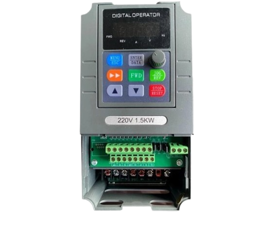
The Yuanshin RS485 Variable Frequency Drive (VFD) is a versatile motor control device designed to regulate the speed and torque of AC motors. By utilizing RS485 communication, this VFD enables seamless integration into industrial automation systems, offering precise control and efficient operation. It is widely used in applications such as conveyor systems, HVAC systems, pumps, and other motor-driven machinery.
Common applications include:
- Industrial automation and process control
- HVAC systems for energy-efficient motor operation
- Conveyor belt speed regulation
- Pump systems for variable flow control
Explore Projects Built with VFD YUANSHIN RS485
 Open Project in Cirkit Designer
 Open Project in Cirkit Designer
 Open Project in Cirkit Designer
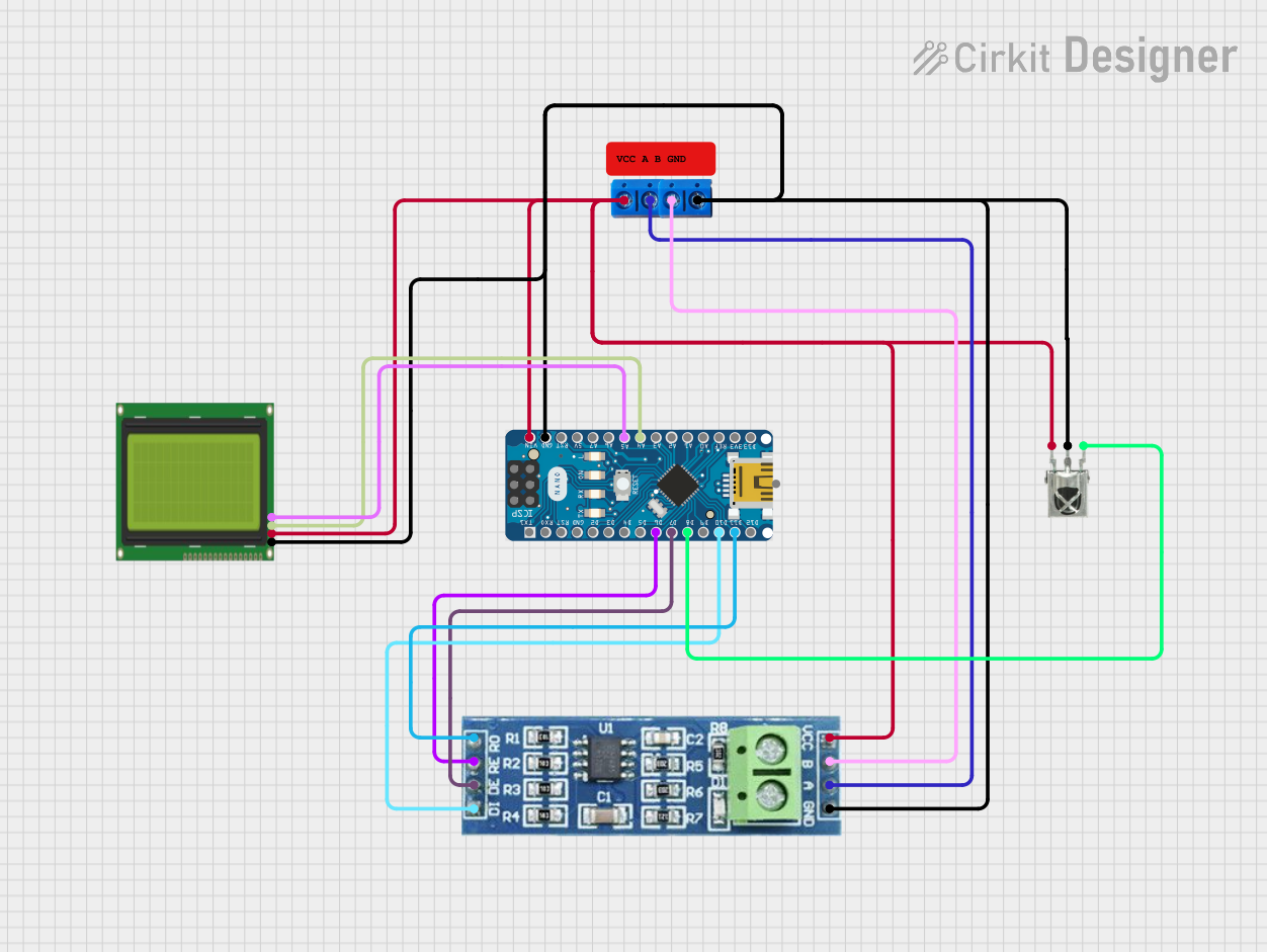 Open Project in Cirkit Designer
Explore Projects Built with VFD YUANSHIN RS485
Open Project in Cirkit DesignerOpen Project in Cirkit DesignerOpen Project in Cirkit DesignerOpen Project in Cirkit DesignerTechnical Specifications
The Yuanshin RS485 VFD is designed to meet the demands of modern automation systems. Below are its key technical details:
General Specifications
| Parameter | Value |
|---|---|
| Input Voltage | 220V AC / 380V AC (single/three-phase) |
| Output Voltage | 0 - Input Voltage |
| Output Frequency Range | 0.1 Hz - 400 Hz |
| Rated Power | 0.75 kW - 15 kW (varies by model) |
| Communication Protocol | RS485 (Modbus RTU) |
| Control Modes | V/F Control, Vector Control |
| Operating Temperature | -10°C to 50°C |
| Protection Features | Overload, Overvoltage, Undervoltage, Short Circuit |
RS485 Pin Configuration
The RS485 communication interface allows for easy integration into automation systems. Below is the pin configuration for the RS485 terminal:
| Pin Number | Label | Description |
|---|---|---|
| 1 | A(+) | RS485 Data Line Positive |
| 2 | B(-) | RS485 Data Line Negative |
| 3 | GND | Ground Reference for RS485 Signal |
Control Terminal Pin Configuration
The control terminals provide additional functionality for external control and monitoring:
| Pin Number | Label | Description |
|---|---|---|
| 1 | FWD | Forward Run Command Input |
| 2 | REV | Reverse Run Command Input |
| 3 | COM | Common Ground for Control Signals |
| 4 | AI | Analog Input (0-10V or 4-20mA) |
| 5 | AO | Analog Output (0-10V) |
| 6 | DI1 | Digital Input 1 |
| 7 | DI2 | Digital Input 2 |
Usage Instructions
Connecting the VFD
- Power Supply: Connect the VFD to the appropriate AC power supply (220V or 380V, depending on the model). Ensure proper grounding to avoid electrical hazards.
- Motor Connection: Connect the motor's three-phase wires to the VFD's output terminals (U, V, W). Verify the motor's rated voltage and current match the VFD's output specifications.
- RS485 Communication:
- Connect the RS485 A(+) and B(-) terminals to the corresponding terminals on the master controller (e.g., PLC or Arduino).
- Use a twisted pair cable for RS485 communication to minimize noise.
- Control Terminals: Wire the control terminals as needed for your application (e.g., forward/reverse commands, analog input for speed control).
Configuring the VFD
- Set Parameters: Use the VFD's keypad or software interface to configure parameters such as motor type, rated voltage, and control mode.
- RS485 Settings:
- Set the communication protocol to Modbus RTU.
- Configure the baud rate, parity, and slave address to match the master controller.
- Test Operation: Run the motor in manual mode to verify proper operation before enabling RS485 control.
Arduino Integration Example
Below is an example of how to control the Yuanshin RS485 VFD using an Arduino UNO and the Modbus RTU protocol:
#include <ModbusMaster.h>

// Instantiate ModbusMaster object
ModbusMaster node;

// Define RS485 communication pins
#define MAX485_DE 3
#define MAX485_RE 2

void preTransmission() {
  digitalWrite(MAX485_DE, HIGH); // Enable RS485 driver
  digitalWrite(MAX485_RE, HIGH); // Disable receiver
}

void postTransmission() {
  digitalWrite(MAX485_DE, LOW);  // Disable RS485 driver
  digitalWrite(MAX485_RE, LOW);  // Enable receiver
}

void setup() {
  // Initialize RS485 control pins
  pinMode(MAX485_DE, OUTPUT);
  pinMode(MAX485_RE, OUTPUT);
  digitalWrite(MAX485_DE, LOW);
  digitalWrite(MAX485_RE, LOW);

  // Initialize Modbus communication
  Serial.begin(9600); // Set baud rate
  node.begin(1, Serial); // Slave ID = 1
  node.preTransmission(preTransmission);
  node.postTransmission(postTransmission);
}

void loop() {
  // Example: Write a frequency setpoint to the VFD
  uint8_t result;
  result = node.writeSingleRegister(0x2000, 50); // Set frequency to 50 Hz

  if (result == node.ku8MBSuccess) {
    Serial.println("Frequency set successfully!");
  } else {
    Serial.print("Error: ");
    Serial.println(result, HEX);
  }

  delay(1000); // Wait 1 second before next command
}
Important Considerations
- Ensure the motor's rated power matches the VFD's capacity to avoid overloading.
- Use shielded cables for RS485 communication to reduce electromagnetic interference.
- Always follow the manufacturer's safety guidelines when installing and operating the VFD.
Troubleshooting and FAQs
Common Issues
Motor Does Not Start:
- Check if the forward/reverse command is properly wired and enabled.
- Verify that the motor parameters (e.g., voltage, current) are correctly configured in the VFD.
RS485 Communication Fails:
- Ensure the baud rate, parity, and slave address match between the VFD and the master controller.
- Check the wiring of the A(+) and B(-) terminals for proper polarity.
Overload or Overvoltage Error:
- Verify that the motor is not drawing more current than the VFD's rated capacity.
- Check the input voltage to ensure it is within the specified range.
FAQs
Q: Can I use the Yuanshin RS485 VFD with a single-phase motor?
A: The VFD is primarily designed for three-phase motors. However, some models may support single-phase motors. Refer to the user manual for compatibility details.
Q: What is the maximum cable length for RS485 communication?
A: The maximum recommended cable length for RS485 is 1200 meters, but this may vary depending on the baud rate and cable quality.
Q: How do I reset the VFD to factory settings?
A: Refer to the VFD's user manual for the specific parameter or procedure to reset all settings to factory defaults.
By following this documentation, users can effectively integrate and operate the Yuanshin RS485 VFD in their automation systems.