Cirkit Designer Logo
Cirkit Designer
Your all-in-one circuit design IDE
Home / 
Component Documentation

How to Use AEAT-601B: Examples, Pinouts, and Specs

Image of AEAT-601B
Cirkit Designer LogoDesign with AEAT-601B in Cirkit Designer

Introduction

The AEAT-601B is a high-performance absolute optical encoder designed to provide precise position feedback in a wide range of applications. Leveraging advanced optical technology, this encoder delivers exceptional resolution and accuracy, making it an ideal choice for demanding environments. Its robust design ensures reliable operation in robotics, industrial automation, and motion control systems.

Explore Projects Built with AEAT-601B

Use Cirkit Designer to design, explore, and prototype these projects online. Some projects support real-time simulation. Click "Open Project" to start designing instantly!
Satellite-Based Timing and Navigation System with SDR and Atomic Clock Synchronization
Image of GPS 시스템 측정 구성도_Confirm: A project utilizing AEAT-601B in a practical application
This circuit appears to be a complex system involving power supply management, GPS and timing synchronization, and data communication. It includes a SI-TEX G1 Satellite Compass for GPS data, an XHTF1021 Atomic Rubidium Clock for precise timing, and Ettus USRP B200 units for software-defined radio communication. Power is supplied through various SMPS units and distributed via terminal blocks and DC jacks. Data communication is facilitated by Beelink MINI S12 N95 computers, RS232 splitters, and a 1000BASE-T Media Converter for network connectivity. RF Directional Couplers are used to interface antennas with the USRP units, and the entire system is likely contained within cases for protection and organization.
Cirkit Designer LogoOpen Project in Cirkit Designer
Battery-Powered Emergency Alert System with NUCLEO-F072RB, SIM800L, and GPS NEO 6M
Image of women safety: A project utilizing AEAT-601B in a practical application
This circuit is an emergency alert system that uses a NUCLEO-F072RB microcontroller to send SMS alerts and make calls via a SIM800L GSM module, while obtaining location data from a GPS NEO 6M module. The system is powered by a Li-ion battery and includes a TP4056 module for battery charging and protection, with a rocker switch to control power to the microcontroller.
Cirkit Designer LogoOpen Project in Cirkit Designer
Solar-Powered GSM/GPRS+GPS Tracker with Seeeduino XIAO
Image of SOS System : A project utilizing AEAT-601B in a practical application
This circuit features an Ai Thinker A9G development board for GSM/GPRS and GPS/BDS connectivity, interfaced with a Seeeduino XIAO microcontroller for control and data processing. A solar cell, coupled with a TP4056 charging module, charges a 3.3V battery, which powers the system through a 3.3V regulator ensuring stable operation. The circuit likely serves for remote data communication and location tracking, with the capability to be powered by renewable energy and interfaced with additional sensors or input devices via the Seeeduino XIAO.
Cirkit Designer LogoOpen Project in Cirkit Designer
Satellite Compass and Network-Integrated GPS Data Processing System
Image of GPS 시스템 측정 구성도_241016: A project utilizing AEAT-601B in a practical application
This circuit comprises a satellite compass, a mini PC, two GPS antennas, power supplies, a network switch, media converters, and an atomic rubidium clock. The satellite compass is powered by a triple output DC power supply and interfaces with an RS232 splitter for 1PPS signals. The mini PCs are connected to the USRP B200 devices via USB for data and power, and to media converters via Ethernet, which in turn connect to a network switch using fiber optic links. The antennas are connected to the USRP B200s through RF directional couplers, and the atomic clock provides a 1PPS input to the RS232 splitter.
Cirkit Designer LogoOpen Project in Cirkit Designer

Explore Projects Built with AEAT-601B

Use Cirkit Designer to design, explore, and prototype these projects online. Some projects support real-time simulation. Click "Open Project" to start designing instantly!
Image of GPS 시스템 측정 구성도_Confirm: A project utilizing AEAT-601B in a practical application
Satellite-Based Timing and Navigation System with SDR and Atomic Clock Synchronization
This circuit appears to be a complex system involving power supply management, GPS and timing synchronization, and data communication. It includes a SI-TEX G1 Satellite Compass for GPS data, an XHTF1021 Atomic Rubidium Clock for precise timing, and Ettus USRP B200 units for software-defined radio communication. Power is supplied through various SMPS units and distributed via terminal blocks and DC jacks. Data communication is facilitated by Beelink MINI S12 N95 computers, RS232 splitters, and a 1000BASE-T Media Converter for network connectivity. RF Directional Couplers are used to interface antennas with the USRP units, and the entire system is likely contained within cases for protection and organization.
Cirkit Designer LogoOpen Project in Cirkit Designer
Image of women safety: A project utilizing AEAT-601B in a practical application
Battery-Powered Emergency Alert System with NUCLEO-F072RB, SIM800L, and GPS NEO 6M
This circuit is an emergency alert system that uses a NUCLEO-F072RB microcontroller to send SMS alerts and make calls via a SIM800L GSM module, while obtaining location data from a GPS NEO 6M module. The system is powered by a Li-ion battery and includes a TP4056 module for battery charging and protection, with a rocker switch to control power to the microcontroller.
Cirkit Designer LogoOpen Project in Cirkit Designer
Image of SOS System : A project utilizing AEAT-601B in a practical application
Solar-Powered GSM/GPRS+GPS Tracker with Seeeduino XIAO
This circuit features an Ai Thinker A9G development board for GSM/GPRS and GPS/BDS connectivity, interfaced with a Seeeduino XIAO microcontroller for control and data processing. A solar cell, coupled with a TP4056 charging module, charges a 3.3V battery, which powers the system through a 3.3V regulator ensuring stable operation. The circuit likely serves for remote data communication and location tracking, with the capability to be powered by renewable energy and interfaced with additional sensors or input devices via the Seeeduino XIAO.
Cirkit Designer LogoOpen Project in Cirkit Designer
Image of GPS 시스템 측정 구성도_241016: A project utilizing AEAT-601B in a practical application
Satellite Compass and Network-Integrated GPS Data Processing System
This circuit comprises a satellite compass, a mini PC, two GPS antennas, power supplies, a network switch, media converters, and an atomic rubidium clock. The satellite compass is powered by a triple output DC power supply and interfaces with an RS232 splitter for 1PPS signals. The mini PCs are connected to the USRP B200 devices via USB for data and power, and to media converters via Ethernet, which in turn connect to a network switch using fiber optic links. The antennas are connected to the USRP B200s through RF directional couplers, and the atomic clock provides a 1PPS input to the RS232 splitter.
Cirkit Designer LogoOpen Project in Cirkit Designer

Common Applications

  • Robotics: For precise joint or wheel position feedback.
  • Industrial Automation: Used in conveyor systems, CNC machines, and assembly lines.
  • Motion Control Systems: Provides accurate position data for motors and actuators.
  • Medical Equipment: Ensures precision in devices like robotic surgical arms.
  • Aerospace: Used in navigation and control systems requiring high accuracy.

Technical Specifications

Key Technical Details

Parameter Value
Operating Voltage 5 V DC ± 10%
Current Consumption 30 mA (typical)
Resolution Up to 12 bits (4096 positions per revolution)
Output Format Parallel Gray Code
Operating Temperature -40°C to +125°C
Maximum Rotational Speed 10,000 RPM
Shaft Diameter 6 mm
Mounting Type Flange Mount

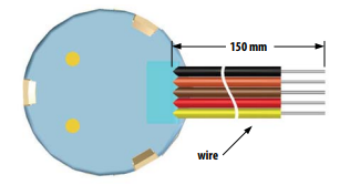
Pin Configuration and Descriptions

Pin Number Pin Name Description
1 VCC Power supply input (5 V DC)
2 GND Ground
3-14 DATA[11:0] Parallel Gray Code output (12-bit data)
15 NC Not connected
16 NC Not connected

Usage Instructions

How to Use the AEAT-601B in a Circuit

  1. Power Supply: Connect the VCC pin to a stable 5 V DC power source and the GND pin to the ground of your circuit.
  2. Data Output: The encoder outputs a 12-bit parallel Gray Code representing the absolute position. Connect the DATA[11:0] pins to a microcontroller or digital input device capable of decoding Gray Code.
  3. Mounting: Secure the encoder using the flange mount and ensure the shaft is properly aligned with the rotating element.
  4. Decoding Gray Code: Use a microcontroller or dedicated decoder to convert the Gray Code output into binary or decimal format for position calculations.

Important Considerations and Best Practices

  • Power Stability: Ensure the power supply is stable and within the specified range to avoid erratic behavior.
  • Signal Integrity: Use short, shielded cables for the data lines to minimize noise and interference.
  • Alignment: Properly align the encoder shaft with the rotating element to prevent mechanical stress.
  • Temperature Range: Operate the encoder within the specified temperature range to ensure accuracy and longevity.
  • Gray Code Decoding: If using an Arduino UNO, you can implement a Gray Code to binary conversion algorithm in your code.

Example Arduino Code

// Example code to read and decode Gray Code from AEAT-601B using Arduino UNO

// Define the data pins connected to the encoder
const int dataPins[12] = {2, 3, 4, 5, 6, 7, 8, 9, 10, 11, 12, 13};

// Function to convert Gray Code to binary
unsigned int grayToBinary(unsigned int gray) {
  unsigned int binary = gray;
  while (gray >>= 1) {
    binary ^= gray;
  }
  return binary;
}

void setup() {
  Serial.begin(9600); // Initialize serial communication
  // Set data pins as input
  for (int i = 0; i < 12; i++) {
    pinMode(dataPins[i], INPUT);
  }
}

void loop() {
  unsigned int grayCode = 0;

  // Read the 12-bit Gray Code from the encoder
  for (int i = 0; i < 12; i++) {
    grayCode |= digitalRead(dataPins[i]) << i;
  }

  // Convert Gray Code to binary
  unsigned int position = grayToBinary(grayCode);

  // Print the position to the serial monitor
  Serial.print("Position: ");
  Serial.println(position);

  delay(100); // Delay for stability
}

Troubleshooting and FAQs

Common Issues and Solutions

  1. No Output from Encoder:

    • Cause: Power supply not connected or incorrect voltage.
    • Solution: Verify the VCC and GND connections and ensure the supply voltage is 5 V DC.
  2. Erratic Position Readings:

    • Cause: Electrical noise or interference on data lines.
    • Solution: Use shielded cables and ensure proper grounding.
  3. Incorrect Position Values:

    • Cause: Gray Code not properly decoded.
    • Solution: Check the decoding algorithm in your microcontroller code.
  4. Mechanical Misalignment:

    • Cause: Shaft not properly aligned with the rotating element.
    • Solution: Re-align the encoder and ensure it is securely mounted.

FAQs

Q1: Can the AEAT-601B be used with a 3.3 V system?
A1: No, the AEAT-601B requires a 5 V DC power supply. Use a level shifter if interfacing with a 3.3 V system.

Q2: What is the maximum cable length for data transmission?
A2: For reliable operation, keep the cable length under 1 meter. Use shielded cables to minimize noise.

Q3: How do I interpret the Gray Code output?
A3: The Gray Code must be converted to binary using a decoding algorithm. Refer to the example Arduino code provided above.

Q4: Can the encoder operate in harsh environments?
A4: Yes, the AEAT-601B is designed to operate in temperatures ranging from -40°C to +125°C, making it suitable for industrial and outdoor applications.