
How to Use SX1308: Examples, Pinouts, and Specs
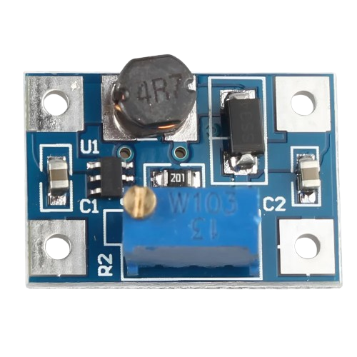
 Design with SX1308 in Cirkit Designer
Introduction
The SX1308 is a highly integrated LoRaWAN gateway chip designed for long-range, low-power wireless communication. It is a key component in building LoRaWAN gateways, enabling communication between end devices and network servers. The SX1308 supports multiple channels and can handle a large number of simultaneous connections, making it ideal for Internet of Things (IoT) applications. Its robust design ensures reliable performance in industrial, agricultural, and smart city deployments.
Explore Projects Built with SX1308
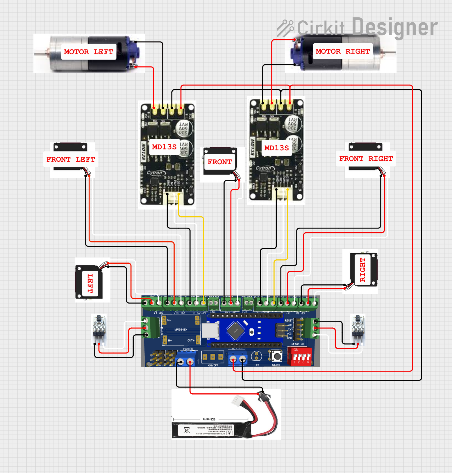
 Open Project in Cirkit Designer
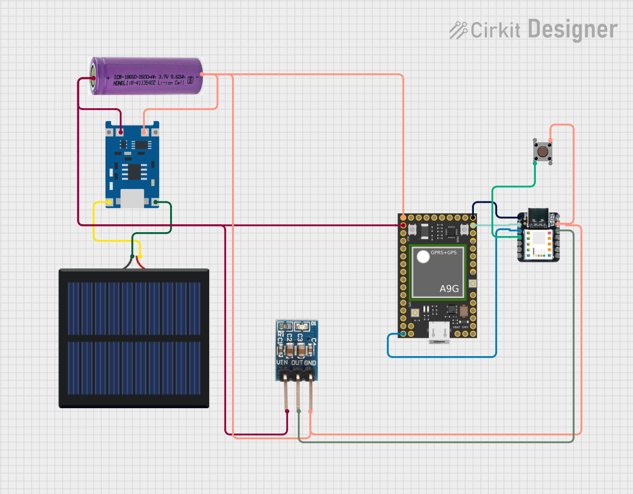
 Open Project in Cirkit Designer
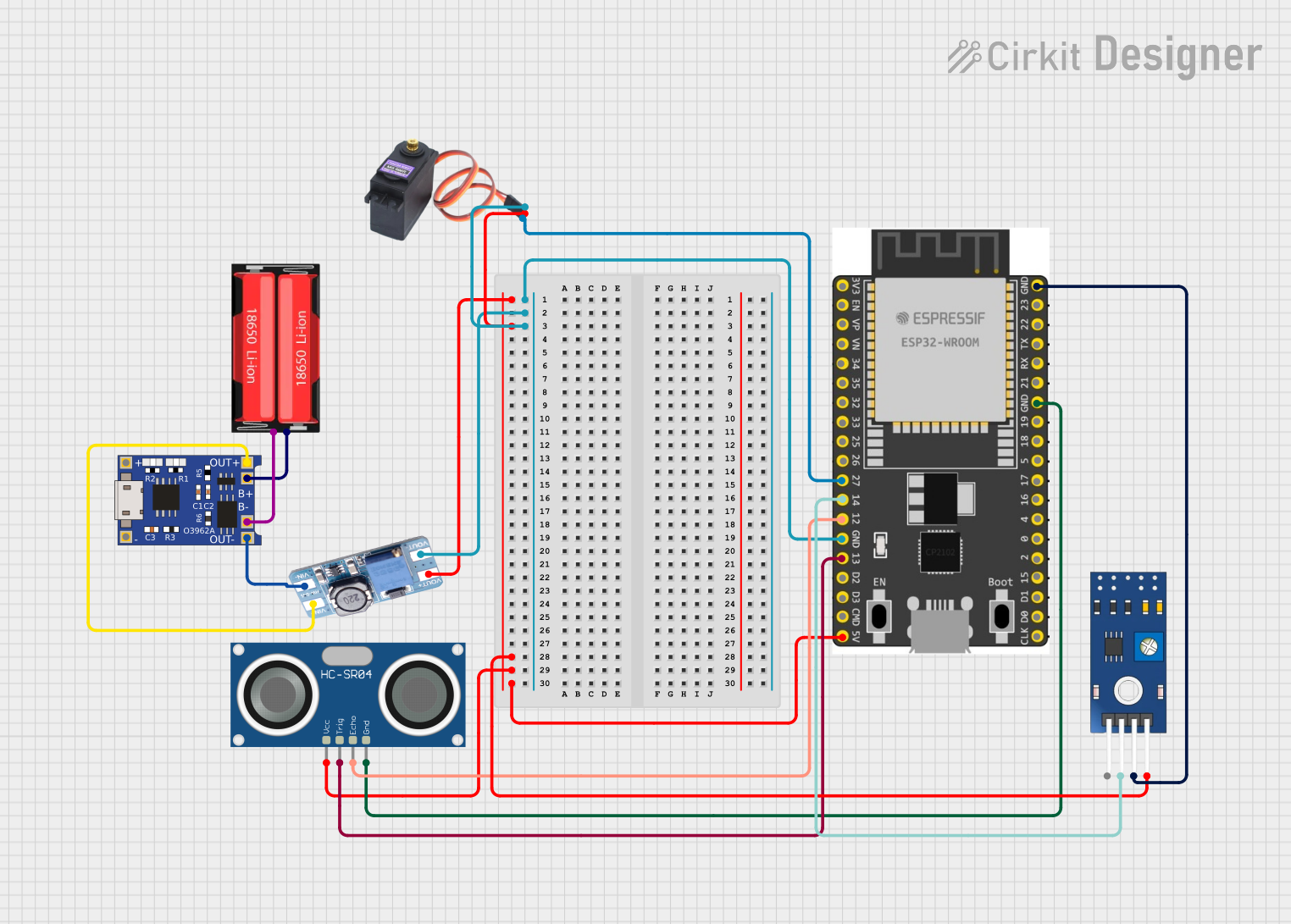
 Open Project in Cirkit Designer
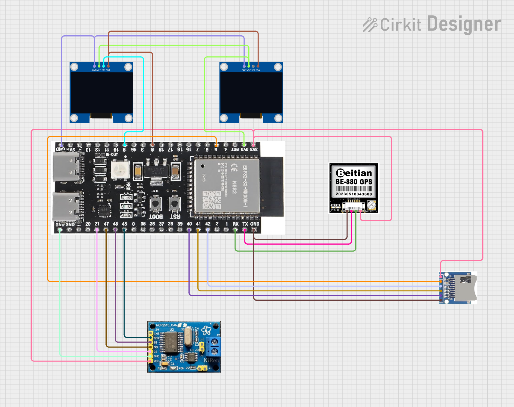
 Open Project in Cirkit Designer
Explore Projects Built with SX1308

 Open Project in Cirkit Designer
 Open Project in Cirkit Designer
 Open Project in Cirkit Designer
 Open Project in Cirkit Designer
Common Applications and Use Cases
- LoRaWAN gateways for IoT networks
- Smart city infrastructure (e.g., smart lighting, parking systems)
- Industrial monitoring and control systems
- Agricultural IoT (e.g., soil moisture sensors, weather stations)
- Environmental monitoring (e.g., air quality sensors)
Technical Specifications
The SX1308 is designed to meet the demanding requirements of LoRaWAN gateways. Below are its key technical specifications:
Key Technical Details
- Frequency Bands: 433 MHz, 868 MHz, 915 MHz (region-specific)
- Number of Channels: Up to 8 uplink channels and 1 downlink channel
- Modulation: LoRa and FSK
- Sensitivity: Down to -137 dBm
- Maximum Output Power: +27 dBm
- Operating Voltage: 3.3V
- Power Consumption:
- Active mode: ~1.2W
- Sleep mode: ~10 mW
- Operating Temperature: -40°C to +85°C
- Package: QFN-64 (9x9 mm)
Pin Configuration and Descriptions
The SX1308 comes in a QFN-64 package with the following pin configuration:
| Pin Number | Pin Name | Description |
|---|---|---|
| 1-8 | RF_IN1-8 | RF input pins for uplink channels |
| 9-16 | RF_OUT | RF output pin for downlink channel |
| 17-24 | GND | Ground pins |
| 25-32 | VDD | Power supply pins (3.3V) |
| 33-40 | SPI_MISO | SPI interface - Master In Slave Out |
| 41-48 | SPI_MOSI | SPI interface - Master Out Slave In |
| 49-56 | SPI_CLK | SPI clock |
| 57-64 | RESET | Reset pin (active low) |
Usage Instructions
The SX1308 is typically used in LoRaWAN gateway designs. Below are the steps and considerations for using the component effectively:
How to Use the SX1308 in a Circuit
- Power Supply: Provide a stable 3.3V power supply to the VDD pins. Ensure proper decoupling capacitors are placed close to the power pins to minimize noise.
- RF Connections: Connect the RF_IN pins to the appropriate antennas for uplink channels. Use impedance-matched traces for RF signals to minimize losses.
- SPI Interface: Use the SPI interface to communicate with the SX1308. Connect the SPI_MISO, SPI_MOSI, and SPI_CLK pins to the microcontroller or processor.
- Reset: Connect the RESET pin to the microcontroller for initialization. Pull the pin low to reset the chip.
- Clock Source: Provide an external clock source (e.g., 32 MHz crystal oscillator) for proper operation.
Important Considerations and Best Practices
- Antenna Design: Use high-quality antennas and ensure proper placement to maximize range and minimize interference.
- Thermal Management: The SX1308 can generate heat during operation. Use a proper heat sink or thermal vias to dissipate heat effectively.
- Firmware Updates: Ensure the firmware on the microcontroller or processor is compatible with the SX1308 to avoid communication issues.
- Regulatory Compliance: Verify that the frequency band and output power comply with local regulations.
Example Code for Arduino UNO
The SX1308 is not directly compatible with Arduino UNO due to its complexity, but it can be interfaced using an SPI library. Below is an example of initializing the SPI interface:
#include <SPI.h>

// Define SX1308 SPI pins
#define SX1308_CS 10  // Chip Select pin
#define SX1308_RST 9  // Reset pin

void setup() {
  // Initialize Serial Monitor
  Serial.begin(9600);
  Serial.println("Initializing SX1308...");

  // Initialize SPI
  SPI.begin();
  pinMode(SX1308_CS, OUTPUT);
  pinMode(SX1308_RST, OUTPUT);

  // Reset the SX1308
  digitalWrite(SX1308_RST, LOW);  // Pull reset pin low
  delay(100);                     // Wait for 100ms
  digitalWrite(SX1308_RST, HIGH); // Release reset pin
  delay(100);

  Serial.println("SX1308 Initialized.");
}

void loop() {
  // Example: Send a dummy command to SX1308
  digitalWrite(SX1308_CS, LOW);  // Select the SX1308
  SPI.transfer(0x00);            // Send a dummy byte
  digitalWrite(SX1308_CS, HIGH); // Deselect the SX1308

  delay(1000); // Wait for 1 second
}
Troubleshooting and FAQs
Common Issues and Solutions
No Communication with SX1308
- Cause: Incorrect SPI connections or configuration.
- Solution: Verify the SPI pin connections and ensure the SPI clock speed is within the SX1308's supported range.
Poor RF Performance
- Cause: Improper antenna design or placement.
- Solution: Use a high-quality antenna and ensure it is placed away from sources of interference.
Overheating
- Cause: Insufficient thermal management.
- Solution: Add a heat sink or improve PCB thermal design with thermal vias.
Reset Pin Not Working
- Cause: Incorrect reset sequence.
- Solution: Ensure the reset pin is pulled low for at least 100ms before releasing.
FAQs
Q: Can the SX1308 operate on 5V?
A: No, the SX1308 requires a 3.3V power supply. Using 5V can damage the chip.Q: How many devices can the SX1308 handle simultaneously?
A: The SX1308 can handle thousands of devices, depending on the network configuration and traffic.Q: Is the SX1308 compatible with LoRaWAN 1.0.3?
A: Yes, the SX1308 is compatible with LoRaWAN 1.0.3 and earlier versions.Q: Can I use the SX1308 for FSK modulation?
A: Yes, the SX1308 supports both LoRa and FSK modulation.
This documentation provides a comprehensive guide to understanding and using the SX1308. For further details, refer to the official datasheet or contact the manufacturer.