How to Use solar panel: Examples, Pinouts, and Specs
Introduction
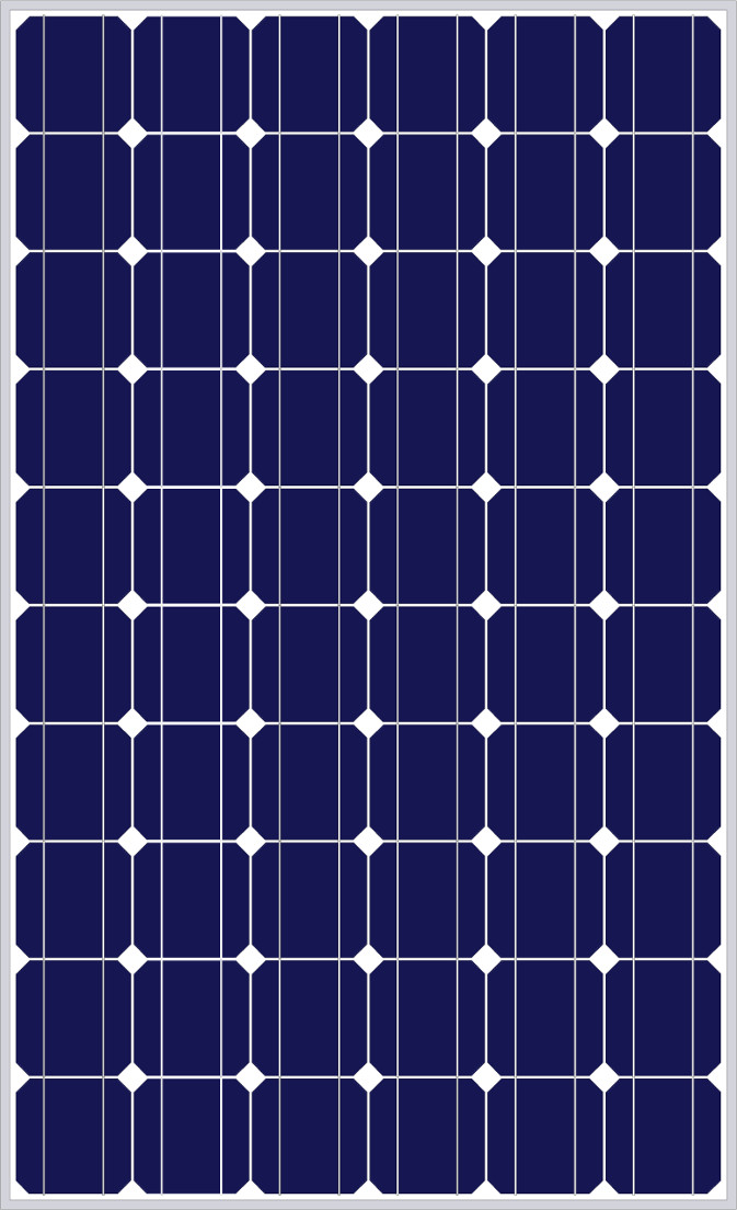
A solar panel, also known as a photovoltaic (PV) panel, is a device that converts sunlight into electrical energy through the photovoltaic effect. Solar panels are composed of many solar cells made of semiconductor materials like silicon. They are widely used in various applications ranging from small-scale systems like solar-powered calculators and residential rooftop installations to large-scale solar farms that feed electricity into the grid.
Explore Projects Built with solar panel

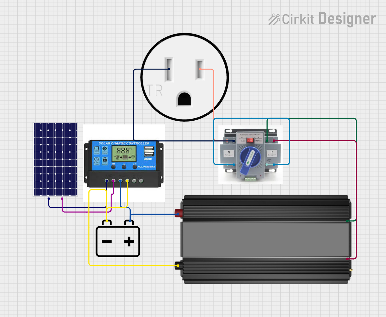
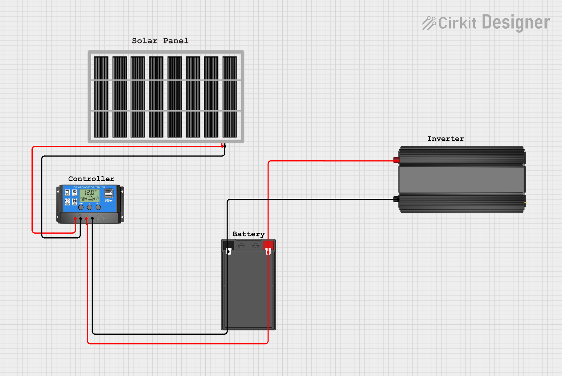
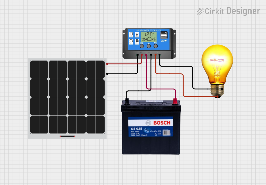
Explore Projects Built with solar panel
Common Applications and Use Cases
- Residential and commercial solar power systems
- Remote power systems for telecommunications and weather stations
- Portable charging systems for devices and batteries
- Solar-powered transportation signals and street lighting
- Spacecraft and satellite power systems
Technical Specifications
Key Technical Details
| Specification | Description |
|---|---|
| Nominal Power (Pmax) | The maximum power output under standard test conditions (STC) |
| Voltage at Pmax (Vmp) | The voltage at which maximum power is available from the panel |
| Current at Pmax (Imp) | The current at which maximum power is available from the panel |
| Open-Circuit Voltage (Voc) | The maximum voltage when no current is flowing |
| Short-Circuit Current (Isc) | The maximum current when the output is shorted |
| Maximum System Voltage | The highest voltage the panel can tolerate |
| Cell Efficiency | The percentage of sunlight converted into electrical energy |
| Operating Temperature Range | The range of temperatures over which the panel can operate effectively |
| Dimensions | The physical size of the panel |
| Weight | The weight of the panel |
Pin Configuration and Descriptions
Solar panels typically do not have "pins" but rather positive and negative terminals. Here is a basic description:
| Terminal | Description |
|---|---|
| Positive (+) | The terminal through which the positive charge flows |
| Negative (−) | The terminal through which the negative charge (or return path) flows |
Usage Instructions
How to Use the Solar Panel in a Circuit
Orientation and Placement: Position the solar panel facing the sun at an angle that maximizes exposure to sunlight. This is typically towards the equator and at an angle equal to the latitude of the location.
Wiring: Connect the positive terminal of the solar panel to the positive input of the charge controller, and the negative terminal to the negative input. Ensure that the wiring is of adequate gauge to handle the current and is properly insulated.
Charge Controller: Always use a charge controller between the solar panel and the battery to prevent overcharging and damage to the battery.
Battery Connection: Connect the charge controller to the battery, ensuring correct polarity. This stores the generated electricity for use when sunlight is not available.
Load Connection: Connect the load to the battery, not directly to the solar panel. This ensures a stable power supply and prevents damage to the load from voltage fluctuations.
Important Considerations and Best Practices
- Avoid Shade: Ensure that the panel is not partially shaded, as this can significantly reduce its output.
- Maintenance: Keep the surface of the panel clean to maintain efficiency.
- Safety: Use appropriate safety equipment when installing the panel, especially on rooftops.
- Regulations: Comply with local regulations and electrical codes when installing solar panels.
Troubleshooting and FAQs
Common Issues
- Reduced Power Output: This can be due to shading, dirt accumulation on the panel surface, or degradation over time.
- No Power Output: Check for loose connections, ensure the panel is facing the sun, and verify that the charge controller and battery are functioning properly.
Solutions and Tips for Troubleshooting
- Cleaning: Regularly clean the panel surface with water and a soft cloth to remove dirt and debris.
- Inspection: Periodically inspect the wiring and connections for signs of wear or damage.
- Testing: Use a multimeter to test the voltage and current output of the panel to ensure it is performing as expected.
FAQs
Q: Can I connect multiple solar panels together? A: Yes, panels can be connected in series to increase voltage or in parallel to increase current, depending on your system requirements.
Q: How long do solar panels last? A: Most solar panels are designed to last 25 years or more, but their efficiency may decrease gradually over time.
Q: Do solar panels work on cloudy days? A: Solar panels can still produce electricity on cloudy days, but their output will be reduced compared to full sunlight conditions.
Q: Is a charge controller always necessary? A: For systems where a battery is used, a charge controller is essential to protect the battery from overcharging and deep discharge.
Example Code for Arduino UNO Connection
// This example assumes the use of a solar panel connected to a charge controller
// and a battery, with the battery then providing power to the Arduino UNO.

void setup() {
  // Initialize the serial communication:
  Serial.begin(9600);
}

void loop() {
  // Assuming a voltage sensor is connected to A0 to measure battery voltage
  int sensorValue = analogRead(A0);
  // Convert the analog reading (which goes from 0 - 1023) to a voltage (0 - 5V):
  float voltage = sensorValue * (5.0 / 1023.0);
  // Print out the voltage to the Serial Monitor
  Serial.println(voltage);

  // Add a delay between readings.
  delay(1000);
}
Note: The above code is a simple demonstration of how to read a voltage level from a sensor connected to an Arduino UNO. It does not directly interact with the solar panel but rather with the system's battery voltage as an indicator of the charge level. Always ensure that the voltage levels are within the acceptable range for the Arduino's analog inputs.