Cirkit Designer Logo
Cirkit Designer
Your all-in-one circuit design IDE
Home / 
Component Documentation

How to Use 5v Battery: Examples, Pinouts, and Specs

Image of 5v Battery
Cirkit Designer LogoDesign with 5v Battery in Cirkit Designer

Introduction

A 5V battery is a portable power source designed to deliver a steady voltage of 5 volts, which is commonly used in a variety of electronic devices and projects. This type of battery is particularly useful for powering small microcontrollers, LED lights, and other components that require a 5V supply. It is a popular choice for hobbyists and professionals alike due to its compatibility with standard logic levels used in digital circuits.

Explore Projects Built with 5v Battery

Use Cirkit Designer to design, explore, and prototype these projects online. Some projects support real-time simulation. Click "Open Project" to start designing instantly!
Battery-Powered LED Indicator with 7805 Voltage Regulator
Image of 5V circuit: A project utilizing 5v Battery in a practical application
This circuit uses a 9V battery to power a 7805 voltage regulator, which outputs a stable 5V. A toggle switch controls the input to the voltage regulator, and the regulated 5V output powers an LED through a 200-ohm resistor, allowing the LED to indicate when the circuit is active.
Cirkit Designer LogoOpen Project in Cirkit Designer
Battery-Powered Fan Circuit
Image of lesson 1: A project utilizing 5v Battery in a practical application
This circuit consists of a 9V battery connected to a fan. The positive terminal of the battery is connected to the 5V pin of the fan, and the negative terminal of the battery is connected to the GND pin of the fan, providing the necessary power for the fan to operate.
Cirkit Designer LogoOpen Project in Cirkit Designer
Battery-Powered ESP32-S3 Development Board Circuit
Image of my esp test: A project utilizing 5v Battery in a practical application
This circuit consists of an ESP32-S3-DevKitC-1-N8R2 microcontroller powered by a 5V battery. The battery's positive terminal is connected to the 5Vin pin of the ESP32, and the negative terminal is connected to the GND pin, providing the necessary power for the microcontroller to operate.
Cirkit Designer LogoOpen Project in Cirkit Designer
Arduino 101 Battery-Powered Fan and Motor Controller with USB Charging
Image of Help 3: A project utilizing 5v Battery in a practical application
This circuit is a battery-powered system that uses a TP4056 module to charge a 7.4V battery, which then powers an Arduino 101, a fan, and a DC motor through a boost converter. The Arduino 101 controls the fan based on the state of a pushbutton, turning it on when the button is pressed.
Cirkit Designer LogoOpen Project in Cirkit Designer

Explore Projects Built with 5v Battery

Use Cirkit Designer to design, explore, and prototype these projects online. Some projects support real-time simulation. Click "Open Project" to start designing instantly!
Image of 5V circuit: A project utilizing 5v Battery in a practical application
Battery-Powered LED Indicator with 7805 Voltage Regulator
This circuit uses a 9V battery to power a 7805 voltage regulator, which outputs a stable 5V. A toggle switch controls the input to the voltage regulator, and the regulated 5V output powers an LED through a 200-ohm resistor, allowing the LED to indicate when the circuit is active.
Cirkit Designer LogoOpen Project in Cirkit Designer
Image of lesson 1: A project utilizing 5v Battery in a practical application
Battery-Powered Fan Circuit
This circuit consists of a 9V battery connected to a fan. The positive terminal of the battery is connected to the 5V pin of the fan, and the negative terminal of the battery is connected to the GND pin of the fan, providing the necessary power for the fan to operate.
Cirkit Designer LogoOpen Project in Cirkit Designer
Image of my esp test: A project utilizing 5v Battery in a practical application
Battery-Powered ESP32-S3 Development Board Circuit
This circuit consists of an ESP32-S3-DevKitC-1-N8R2 microcontroller powered by a 5V battery. The battery's positive terminal is connected to the 5Vin pin of the ESP32, and the negative terminal is connected to the GND pin, providing the necessary power for the microcontroller to operate.
Cirkit Designer LogoOpen Project in Cirkit Designer
Image of Help 3: A project utilizing 5v Battery in a practical application
Arduino 101 Battery-Powered Fan and Motor Controller with USB Charging
This circuit is a battery-powered system that uses a TP4056 module to charge a 7.4V battery, which then powers an Arduino 101, a fan, and a DC motor through a boost converter. The Arduino 101 controls the fan based on the state of a pushbutton, turning it on when the button is pressed.
Cirkit Designer LogoOpen Project in Cirkit Designer

Common Applications and Use Cases

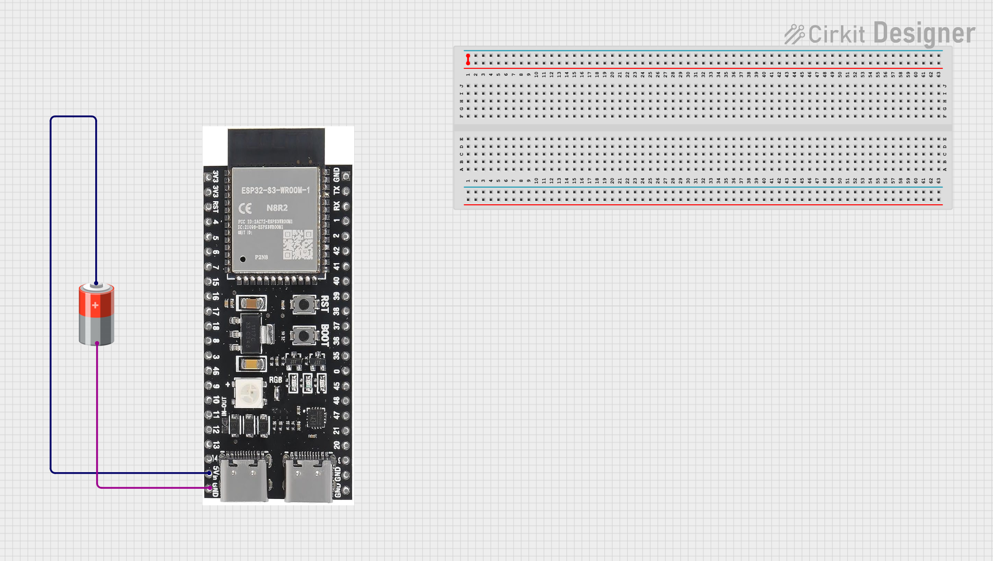
  • Powering microcontrollers such as Arduino and Raspberry Pi
  • Operating portable USB devices
  • Supplying power to LED strips and displays
  • Serving as a backup power source for RTC modules
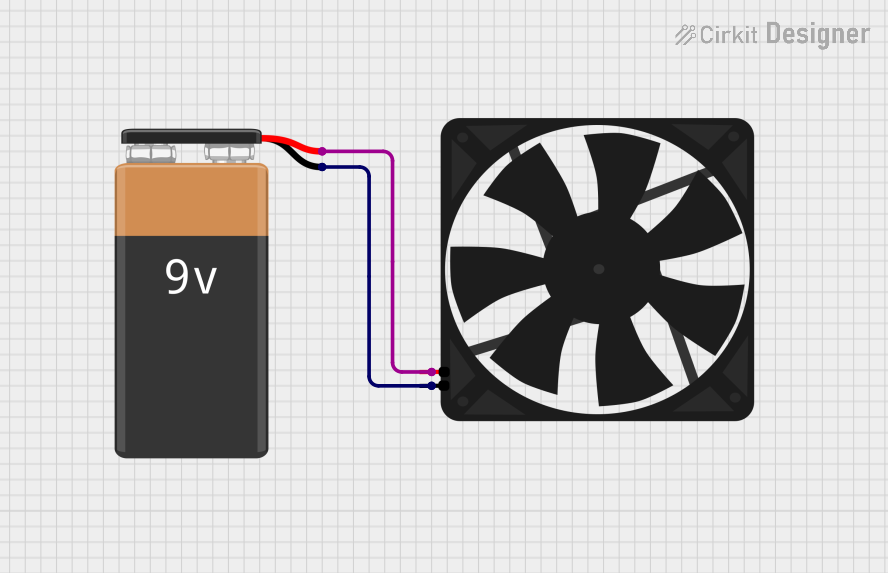
  • Providing energy for small motors and servos in robotics

Technical Specifications

Key Technical Details

  • Nominal Output Voltage: 5V
  • Capacity: Varies by specific model and manufacturer (e.g., 2200mAh, 5000mAh)
  • Chemistry: Typically Lithium Polymer (LiPo) or Lithium-Ion (Li-Ion)
  • Rechargeability: Usually rechargeable
  • Operating Temperature Range: Varies by specific model (e.g., 0°C to 45°C)

Pin Configuration and Descriptions

Pin Number Description Notes
1 Positive (V+) Connect to the positive rail of the circuit
2 Negative (GND) Connect to the ground rail of the circuit

Usage Instructions

How to Use the Component in a Circuit

  1. Connecting the Battery: Identify the positive and negative terminals of the 5V battery. Connect the positive terminal to the VCC or VIN pin of your device, and the negative terminal to the ground (GND) pin.

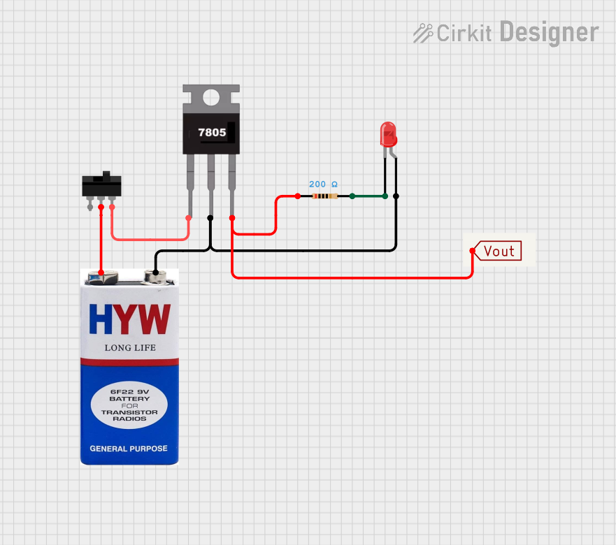
  2. Voltage Regulation (if necessary): If your device requires a regulated 5V supply and the battery does not have a built-in regulator, use a voltage regulator to ensure a stable output.

  3. Monitoring Battery Life: Keep track of the battery's charge level to prevent unexpected power loss. Consider integrating a battery management system if your project requires it.

Important Considerations and Best Practices

  • Polarity: Always ensure correct polarity when connecting the battery to prevent damage to the circuit.
  • Over-Discharge Protection: Avoid discharging the battery below its recommended cutoff voltage to prolong its lifespan.
  • Charging: Use a proper charger that matches the battery's chemistry and specifications.
  • Storage: Store the battery at room temperature in a dry environment when not in use.

Troubleshooting and FAQs

Common Issues Users Might Face

  • Battery not charging: Ensure the charger is functioning and compatible with the battery's chemistry.
  • Reduced runtime: The battery may be nearing the end of its lifespan or may not be fully charged.
  • No power output: Check connections for proper polarity and secure contact.

Solutions and Tips for Troubleshooting

  • Battery Maintenance: Regularly check the battery's voltage and avoid leaving it discharged for extended periods.
  • Connection Issues: Inspect all connections for corrosion or loose wires.
  • Device Compatibility: Verify that the device you're powering can operate at a constant 5V supply.

FAQs

Q: Can I use a 5V battery to power an Arduino UNO? A: Yes, you can power an Arduino UNO with a 5V battery by connecting it to the VIN pin and GND.

Q: How do I recharge a 5V battery? A: Use a charger that is specifically designed for the battery's chemistry and voltage.

Q: What is the lifespan of a 5V battery? A: The lifespan depends on the battery's chemistry, capacity, and usage patterns. Refer to the manufacturer's specifications for more details.

Example Code for Arduino UNO

// This example demonstrates how to power an Arduino UNO with a 5V battery.

void setup() {
  // Initialize digital pin LED_BUILTIN as an output.
  pinMode(LED_BUILTIN, OUTPUT);
}

void loop() {
  // Turn the LED on (HIGH is the voltage level)
  digitalWrite(LED_BUILTIN, HIGH);
  // Wait for a second
  delay(1000);
  // Turn the LED off by making the voltage LOW
  digitalWrite(LED_BUILTIN, LOW);
   // Wait for a second
  delay(1000);
}

Note: This code is a simple blink example that assumes the Arduino UNO is powered by the 5V battery connected to the VIN pin and GND. Always ensure the battery is properly connected and charged before use.