How to Use Main Supply: Examples, Pinouts, and Specs

 Design with Main Supply in Cirkit Designer
Introduction
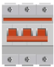
The Main Supply is the primary source of electrical power for a circuit, providing the necessary voltage and current to operate the components within the system. It is a critical component in any electronic design, ensuring that all connected devices receive stable and reliable power. Main Supplies can range from simple batteries to complex regulated power supplies, depending on the application.
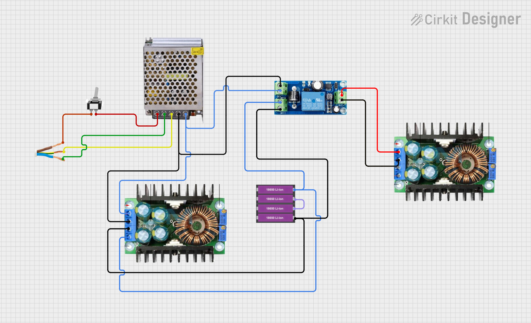
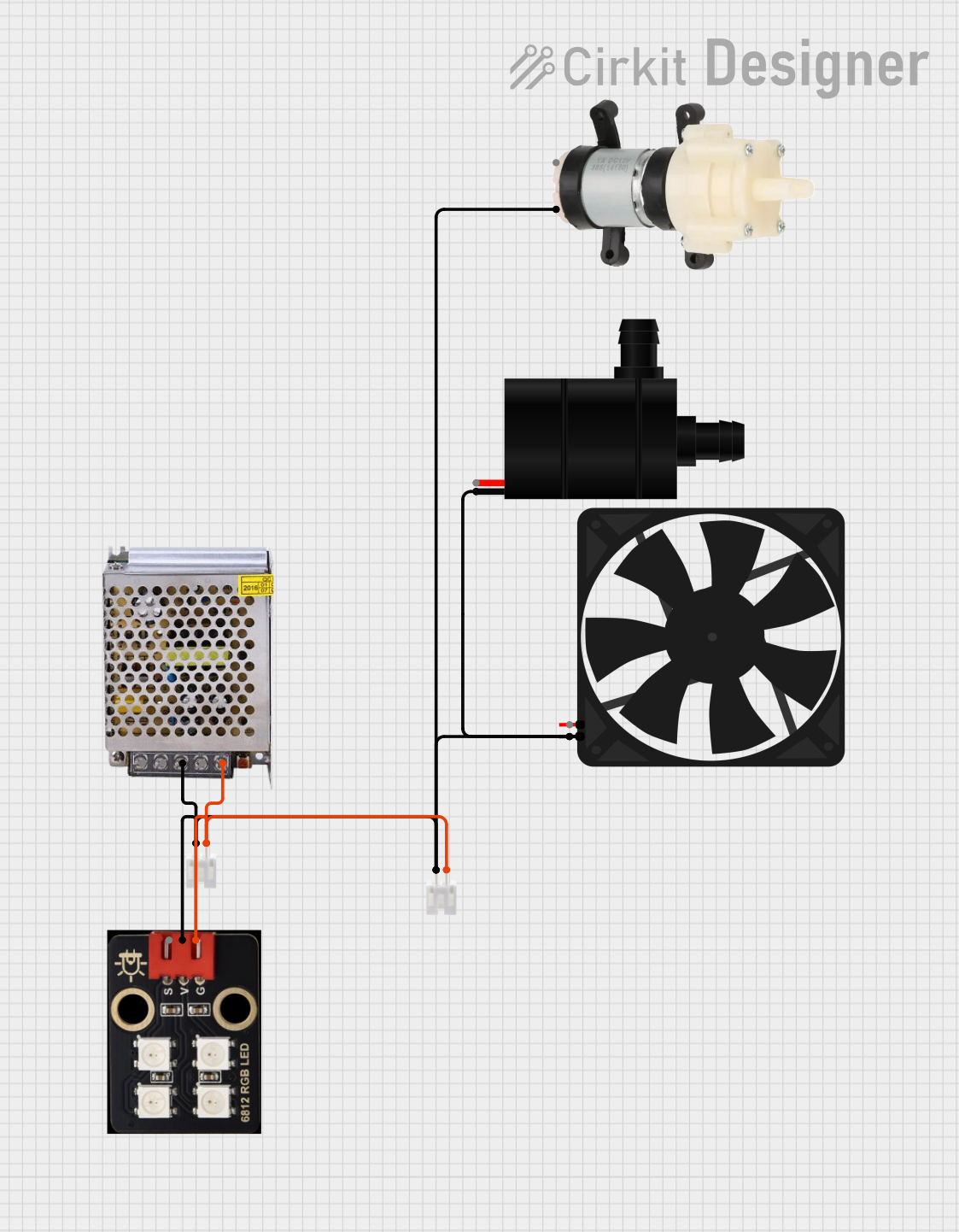
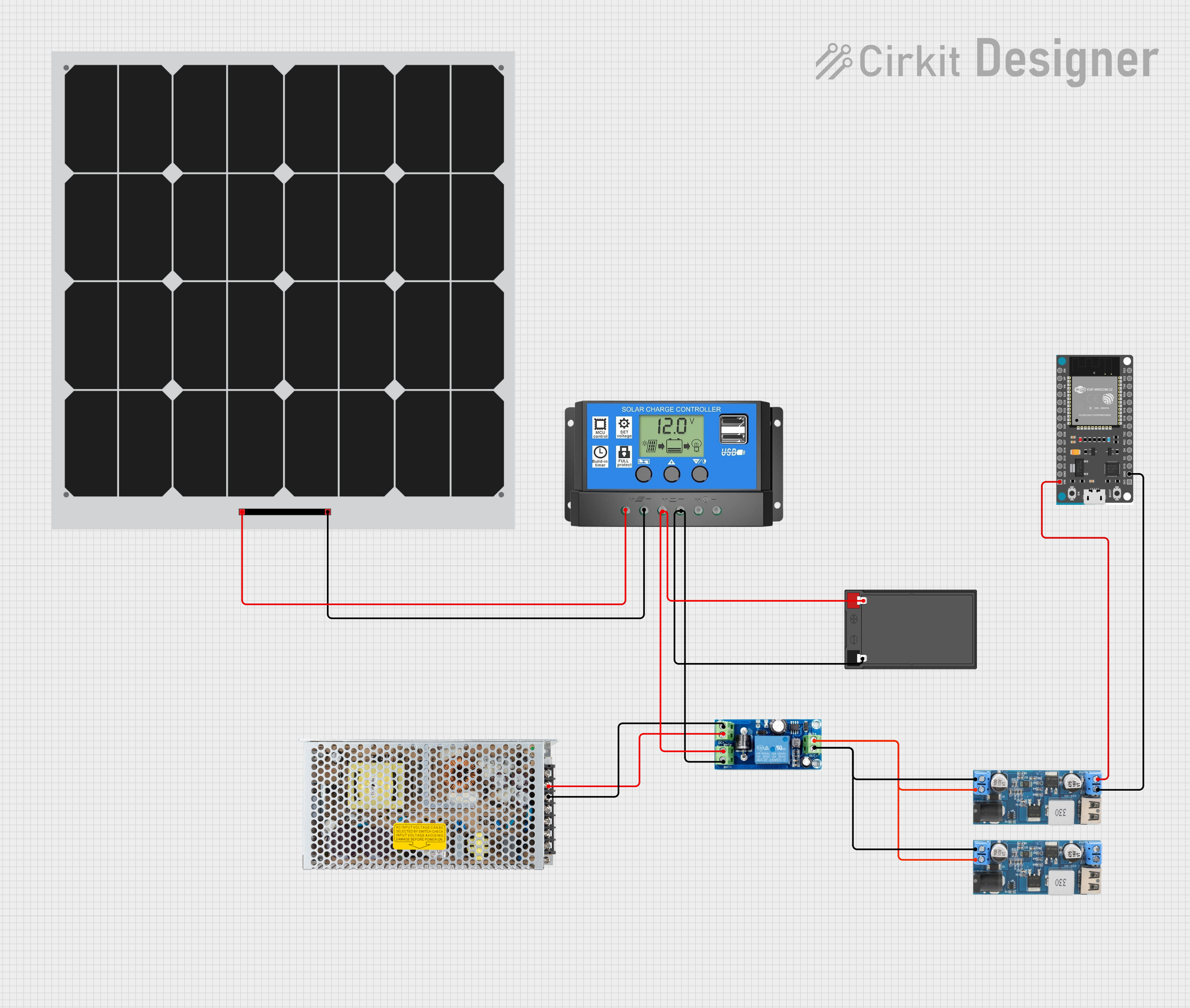
Explore Projects Built with Main Supply

 Open Project in Cirkit Designer
 Open Project in Cirkit Designer
 Open Project in Cirkit Designer
 Open Project in Cirkit Designer
Explore Projects Built with Main Supply

 Open Project in Cirkit Designer
 Open Project in Cirkit Designer
 Open Project in Cirkit Designer
 Open Project in Cirkit Designer
Common Applications and Use Cases
- Powering microcontrollers, sensors, and actuators in embedded systems
- Supplying energy to industrial control systems
- Providing power for consumer electronics such as smartphones, laptops, and appliances
- Driving high-power devices like motors and LEDs
- Serving as a stable voltage source for testing and prototyping circuits
Technical Specifications
The technical specifications of a Main Supply depend on its design and intended use. Below are general parameters to consider:
| Parameter | Description |
|---|---|
| Input Voltage Range | The voltage range the supply can accept as input (e.g., 100-240V AC for AC supplies). |
| Output Voltage | The voltage provided to the circuit (e.g., 5V, 12V, 24V). |
| Output Current | The maximum current the supply can deliver (e.g., 1A, 5A, 10A). |
| Power Rating | The total power the supply can provide, calculated as Voltage × Current (e.g., 50W). |
| Regulation Type | Indicates whether the supply is regulated (constant voltage) or unregulated. |
| Efficiency | The percentage of input power converted to usable output power (e.g., 85%). |
| Protection Features | Overvoltage, overcurrent, short-circuit, and thermal protection mechanisms. |
| Connector Type | The type of output connector (e.g., barrel jack, screw terminals, USB). |
Pin Configuration and Descriptions
For a typical DC Main Supply with screw terminal outputs:
| Pin | Label | Description |
|---|---|---|
| 1 | V+ | Positive voltage output terminal. |
| 2 | V- | Negative voltage (ground) output terminal. |
For an AC-to-DC adapter with a barrel jack:
| Pin | Label | Description |
|---|---|---|
| Center | V+ | Positive voltage output (inner barrel). |
| Outer | V- | Negative voltage (outer barrel, ground). |
Usage Instructions
How to Use the Main Supply in a Circuit
- Determine Voltage and Current Requirements: Identify the voltage and current needs of your circuit components. Ensure the Main Supply can meet these requirements.
- Connect the Output Terminals:
- For screw terminals, connect the V+ terminal to the positive rail of your circuit and the V- terminal to the ground rail.
- For barrel jacks, ensure the polarity matches your circuit's requirements (center-positive or center-negative).
- Power On the Supply: After verifying all connections, turn on the Main Supply. Use a multimeter to confirm the output voltage before connecting sensitive components.
- Monitor the Load: Ensure the total current draw of your circuit does not exceed the supply's maximum current rating.
Important Considerations and Best Practices
- Polarity: Always double-check the polarity of the connections to avoid damaging components.
- Load Regulation: Use a regulated Main Supply for circuits requiring stable voltage, such as microcontroller-based systems.
- Heat Dissipation: Ensure proper ventilation or heat sinking for high-power supplies to prevent overheating.
- Fuse Protection: Use an inline fuse to protect the circuit from overcurrent conditions.
- Arduino Compatibility: When using the Main Supply with an Arduino UNO, ensure the voltage is within the Arduino's input range (7-12V recommended for the barrel jack).
Example: Connecting a Main Supply to an Arduino UNO
// Example code to blink an LED using an Arduino UNO powered by a Main Supply

// Pin configuration
const int ledPin = 13; // Built-in LED pin on Arduino UNO

void setup() {
  pinMode(ledPin, OUTPUT); // Set the LED pin as an output
}

void loop() {
  digitalWrite(ledPin, HIGH); // Turn the LED on
  delay(1000);                // Wait for 1 second
  digitalWrite(ledPin, LOW);  // Turn the LED off
  delay(1000);                // Wait for 1 second
}

// Ensure the Main Supply provides 7-12V to the Arduino's barrel jack or VIN pin.
// Verify the polarity of the connections before powering the Arduino.
Troubleshooting and FAQs
Common Issues and Solutions
No Output Voltage:
- Check if the Main Supply is powered on.
- Verify input connections and ensure the input voltage is within the specified range.
- Inspect for blown fuses or tripped protection circuits.
Overheating:
- Ensure the supply is not overloaded. Reduce the load if necessary.
- Check for proper ventilation and avoid placing the supply in enclosed spaces.
Voltage Drops Under Load:
- Confirm the supply's current rating is sufficient for the connected load.
- Use thicker wires to reduce resistance in high-current applications.
Noise or Ripple in Output:
- Use a regulated Main Supply for sensitive circuits.
- Add decoupling capacitors near the load to filter out noise.
FAQs
Q: Can I use a 12V Main Supply for a 5V circuit?
A: No, you will need a voltage regulator or a DC-DC converter to step down the voltage to 5V.
Q: How do I know if my Main Supply is regulated?
A: Check the product specifications. Regulated supplies maintain a constant output voltage regardless of load variations.
Q: What happens if I exceed the current rating of the Main Supply?
A: The supply may shut down, activate overcurrent protection, or overheat, potentially causing damage.
Q: Can I connect multiple Main Supplies in parallel?
A: Only if the supplies are designed for parallel operation. Otherwise, differences in voltage may cause uneven current sharing or damage.
By following these guidelines and best practices, you can ensure safe and efficient use of your Main Supply in various electronic applications.