How to Use Max98357 : Examples, Pinouts, and Specs
Introduction
The MAX98357 is a high-efficiency, digital pulse-code modulation (PCM) amplifier capable of delivering 3.2W of power into a 4Ω load. It integrates a digital-to-analog converter (DAC) and utilizes pulse-width modulation (PWM) for audio signal amplification. This component is ideal for compact audio applications, such as portable speakers, smartphones, and other devices where space and power efficiency are critical.
Explore Projects Built with Max98357


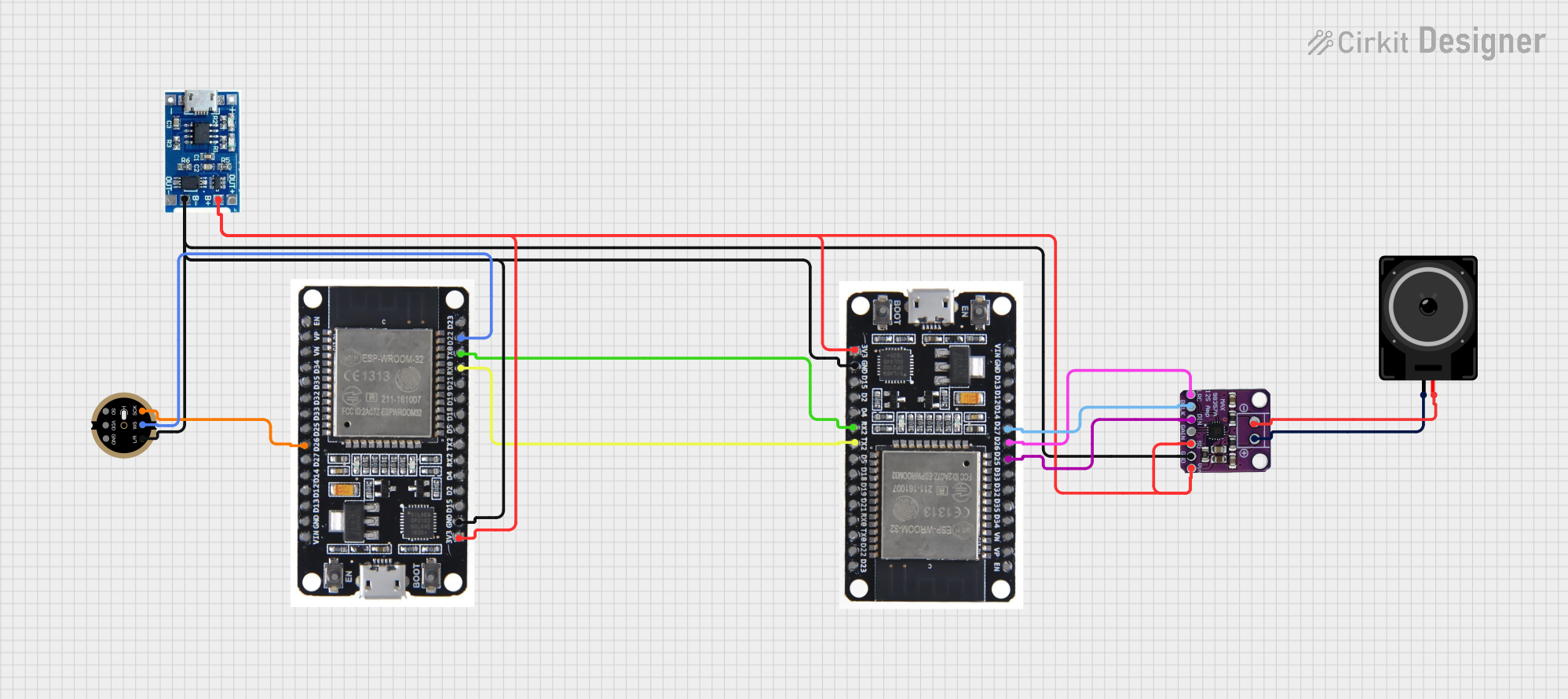
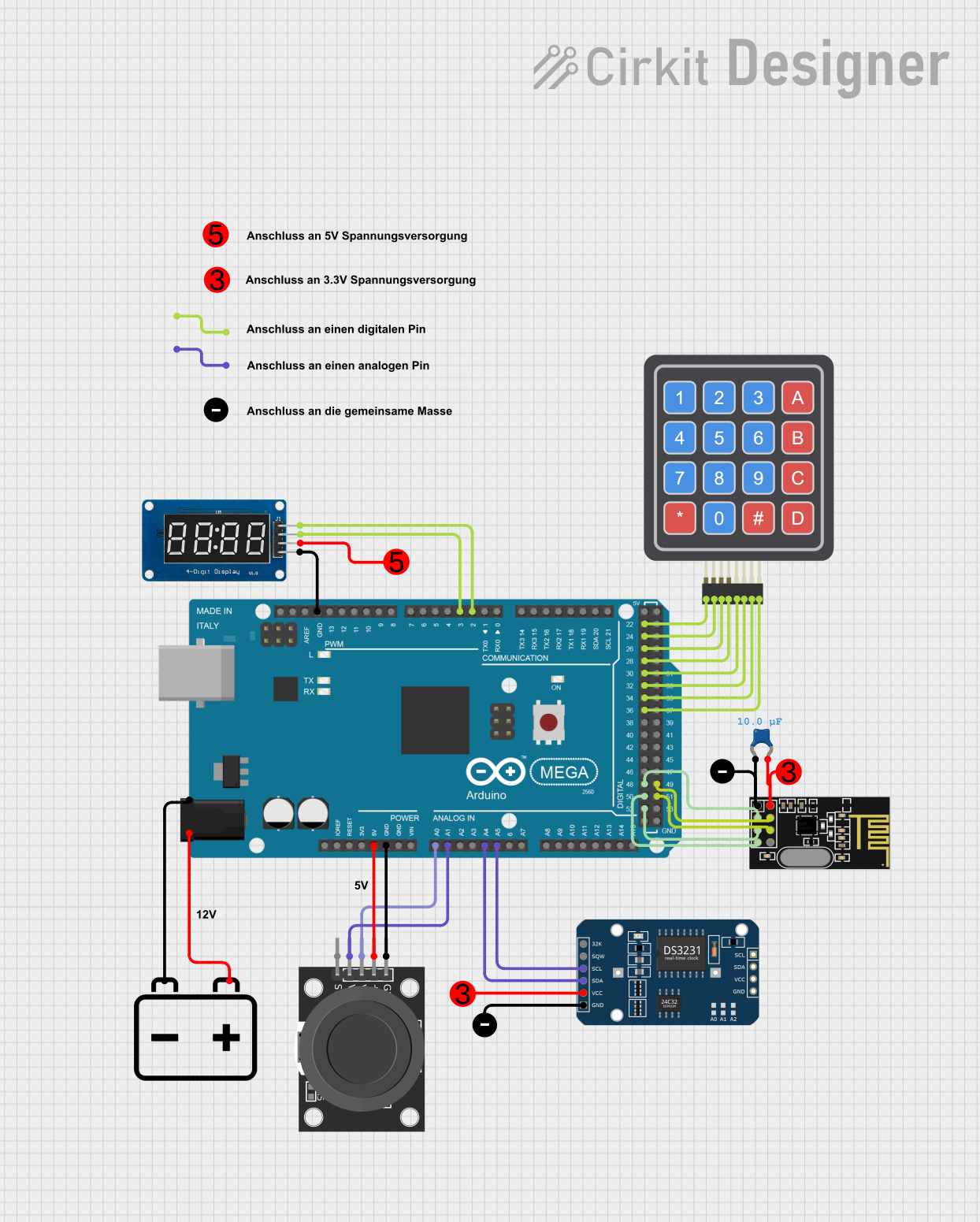
Explore Projects Built with Max98357
Common Applications and Use Cases
- Portable Bluetooth speakers
- DIY audio projects with microcontrollers (e.g., Arduino)
- Low-power audio systems for toys and gadgets
- Soundbars and small home audio devices
Technical Specifications
Key Technical Details
- Supply Voltage (V_DD): 2.5V to 5.5V
- Output Power: 3.2W into 4Ω at 5V
- Digital Audio Interface: I²S
- THD+N: 0.1% (Typical at 1kHz)
- SNR: 90dB (Typical)
- Efficiency: Up to 92%
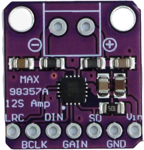
Pin Configuration and Descriptions
| Pin Number | Name | Description |
|---|---|---|
| 1 | LRC | Left/Right Clock Input |
| 2 | BCLK | Bit Clock Input |
| 3 | DIN | Digital Audio Data Input |
| 4 | GAIN | Gain Select Input |
| 5 | SD | Shutdown Control Input |
| 6 | GND | Ground |
| 7 | V_DD | Supply Voltage |
| 8 | OUT+ | Positive Speaker Output |
| 9 | OUT- | Negative Speaker Output |
Usage Instructions
How to Use the MAX98357 in a Circuit
Power Supply: Connect the V_DD pin to a clean power supply ranging from 2.5V to 5.5V. Ensure that the power supply can deliver sufficient current for the desired output power.
Audio Input: The MAX98357 accepts digital I²S audio input. Connect the LRC, BCLK, and DIN pins to the corresponding outputs of your audio source, such as a microcontroller or another digital audio source.
Gain Setting: The GAIN pin can be used to select different gain settings for the amplifier. Connect this pin to V_DD, GND, or leave it floating as per the desired gain level.
Shutdown Control: The SD pin is used to put the amplifier into a low-power shutdown mode. Drive this pin low to shut down the amplifier, or connect it to V_DD to keep the amplifier active.
Speaker Connection: Connect your 4Ω speaker to the OUT+ and OUT- pins. Ensure that the speaker's power rating is compatible with the amplifier's output.
Important Considerations and Best Practices
- Use decoupling capacitors close to the V_DD and GND pins to minimize power supply noise.
- Keep the audio signal paths as short as possible to reduce the risk of electromagnetic interference (EMI).
- Ensure proper heat dissipation if the amplifier is expected to operate at high output power levels for extended periods.
- Avoid running signal lines parallel to high-current paths to prevent crosstalk.
Troubleshooting and FAQs
Common Issues
- No Sound Output: Check the power supply, ensure that the SD pin is not driving the amplifier into shutdown mode, and verify that the I²S connections are correct.
- Distorted Sound: Ensure that the power supply is stable and that the gain setting is appropriate for the input signal level.
- Overheating: Make sure that the amplifier is not being overdriven and that there is adequate ventilation around the component.
Solutions and Tips for Troubleshooting
- Use an oscilloscope to check the I²S signals for integrity.
- If using with a microcontroller like Arduino, ensure that the I²S library is correctly configured for the MAX98357.
- Check solder joints and wiring for any shorts or open connections.
FAQs
Q: Can the MAX98357 be used with an 8Ω speaker? A: Yes, but the output power will be lower compared to using a 4Ω speaker.
Q: What is the maximum supply voltage for the MAX98357? A: The maximum supply voltage is 5.5V. Exceeding this voltage can damage the amplifier.
Q: How do I change the gain setting on the MAX98357? A: The gain can be adjusted by connecting the GAIN pin to different voltage levels as specified in the datasheet.
Example Code for Arduino UNO
#include <Arduino.h>
#include <Wire.h>
#include <I2S.h>

// Define the I2S pins for the Arduino UNO
#define I2S_DIN   11
#define I2S_BCLK  13
#define I2S_LRC   10

void setup() {
  // Initialize I2S with the standard format for MAX98357
  I2S.begin(I2S_PHILIPS_MODE, I2S_16BIT, I2S_44KHZ);
}

void loop() {
  // Example: Send a 440Hz sine wave to the MAX98357
  int sample;
  for (int i = 0; i < 100; i++) {
    sample = sin(i * 2 * PI / 100) * 32767;
    I2S.write(sample); // Write audio sample to MAX98357
  }
}
Note: This example assumes that you have connected the I2S pins of the Arduino UNO to the corresponding pins on the MAX98357. Adjust the pin definitions and I2S settings as needed for your specific setup.