How to Use IRLZ44N: Examples, Pinouts, and Specs
Introduction
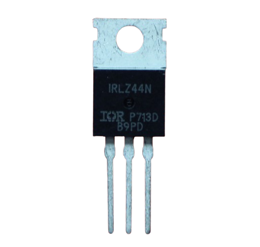
The IRLZ44N is an N-channel MOSFET (Metal-Oxide-Semiconductor Field-Effect Transistor) designed for high-speed switching applications. It features a low on-resistance (RDS(on)), enabling it to handle high currents efficiently with minimal power loss. This makes the IRLZ44N an ideal choice for power management, motor control, LED drivers, and other applications requiring efficient switching and current handling.
Explore Projects Built with IRLZ44N


Explore Projects Built with IRLZ44N
Common Applications:
- DC motor control in robotics and automation
- LED dimming and lighting systems
- Power management in battery-operated devices
- High-speed switching in power supplies
- Inverter circuits and H-bridge configurations
Technical Specifications
Key Technical Details:
| Parameter | Value |
|---|---|
| Type | N-Channel MOSFET |
| Maximum Drain-Source Voltage (VDS) | 55V |
| Maximum Gate-Source Voltage (VGS) | ±16V |
| Continuous Drain Current (ID) | 47A (at 25°C) |
| Pulsed Drain Current (IDM) | 160A |
| On-Resistance (RDS(on)) | 0.022Ω (at VGS = 10V) |
| Gate Threshold Voltage (VGS(th)) | 1V to 2V |
| Power Dissipation (PD) | 94W |
| Operating Temperature Range | -55°C to +175°C |
| Package Type | TO-220 |
Pin Configuration:
The IRLZ44N comes in a TO-220 package with three pins. The pinout is as follows:
| Pin Number | Name | Description |
|---|---|---|
| 1 | Gate | Controls the MOSFET's switching state. A voltage applied here turns the MOSFET on or off. |
| 2 | Drain | The main current-carrying terminal. Connect to the load. |
| 3 | Source | The return path for current. Typically connected to ground. |
Usage Instructions
How to Use the IRLZ44N in a Circuit:
- Gate Control: Apply a voltage to the Gate (Pin 1) to control the MOSFET. A voltage of 5V or higher (logic-level) is sufficient to fully turn on the IRLZ44N.
- Drain-Source Path: Connect the load between the Drain (Pin 2) and the positive supply voltage. The Source (Pin 3) is typically connected to ground.
- Gate Resistor: Use a resistor (e.g., 220Ω to 1kΩ) between the Gate and the control signal to limit inrush current and protect the driving circuit.
- Flyback Diode: When driving inductive loads (e.g., motors, relays), add a flyback diode across the load to protect the MOSFET from voltage spikes.
Example Circuit with Arduino UNO:
The IRLZ44N can be used to control a DC motor with an Arduino UNO. Below is an example circuit and code:
Circuit Connections:
- Gate (Pin 1): Connect to Arduino digital pin (e.g., D9) through a 220Ω resistor.
- Drain (Pin 2): Connect to one terminal of the motor.
- Source (Pin 3): Connect to ground.
- Motor: Connect the other terminal to the positive supply (e.g., 12V).
- Flyback Diode: Place a diode (e.g., 1N4007) across the motor terminals, with the cathode connected to the positive supply.
Arduino Code:
// IRLZ44N MOSFET Example: Controlling a DC motor with Arduino UNO
const int motorPin = 9; // Pin connected to the Gate of the IRLZ44N

void setup() {
  pinMode(motorPin, OUTPUT); // Set motorPin as an output
}

void loop() {
  analogWrite(motorPin, 128); // Set motor speed to 50% (PWM value: 128)
  delay(5000);               // Run motor for 5 seconds
  analogWrite(motorPin, 0);  // Turn off motor
  delay(5000);               // Wait for 5 seconds
}
Important Considerations:
- Ensure the Gate voltage (VGS) is within the specified range (0V to 16V).
- Use a heatsink if the MOSFET is expected to handle high currents for extended periods.
- Avoid exceeding the maximum Drain-Source voltage (55V) to prevent damage.
- For PWM control, ensure the frequency is within the MOSFET's switching speed capabilities.
Troubleshooting and FAQs
Common Issues and Solutions:
MOSFET Not Turning On:
- Ensure the Gate voltage is at least 5V (logic-level) for full turn-on.
- Check for a proper connection between the Gate and the control signal.
Excessive Heat Generation:
- Verify that the MOSFET is operating within its current and voltage ratings.
- Use a heatsink to dissipate heat during high-current operation.
Motor Not Running:
- Check the connections between the MOSFET, motor, and power supply.
- Ensure the flyback diode is correctly oriented to protect the MOSFET.
MOSFET Fails or Shorts:
- Avoid voltage spikes by using a flyback diode for inductive loads.
- Ensure the Gate voltage does not exceed ±16V.
FAQs:
Q1: Can the IRLZ44N be driven directly by a 3.3V microcontroller?
A1: While the IRLZ44N is a logic-level MOSFET, it performs best with a Gate voltage of 5V or higher. At 3.3V, it may not fully turn on, leading to higher RDS(on) and heat generation.
Q2: Is the IRLZ44N suitable for high-frequency switching?
A2: Yes, the IRLZ44N can handle high-frequency switching, but ensure the Gate driver circuit can supply sufficient current to charge and discharge the Gate capacitance quickly.
Q3: Can I use the IRLZ44N for AC loads?
A3: The IRLZ44N is designed for DC applications. For AC loads, consider using a TRIAC or an H-bridge configuration with appropriate control circuitry.
Q4: Do I need a heatsink for low-current applications?
A4: No, a heatsink is not necessary for low-current applications. However, for currents approaching the maximum rating, a heatsink is recommended to prevent overheating.