How to Use RK3588S: Examples, Pinouts, and Specs
Introduction
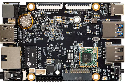
The RK3588S, manufactured by Firefly, is a high-performance system-on-chip (SoC) designed for demanding applications in artificial intelligence (AI), multimedia processing, and edge computing. It features an octa-core CPU architecture, a powerful GPU, and support for 8K video output. This SoC is ideal for use in embedded systems, consumer electronics, and industrial applications requiring advanced processing capabilities.
Explore Projects Built with RK3588S


Explore Projects Built with RK3588S
Common Applications and Use Cases
- AI-based edge computing and inference
- 8K video playback and streaming
- Smart home devices and IoT hubs
- Industrial automation and robotics
- Digital signage and interactive displays
- High-performance gaming consoles
- Multimedia processing and video editing systems
Technical Specifications
Key Technical Details
| Specification | Description |
|---|---|
| CPU | Octa-core processor: 4x Cortex-A76 + 4x Cortex-A55 |
| GPU | ARM Mali-G610 MP4 |
| AI Accelerator | Built-in NPU with up to 6 TOPS (Tera Operations Per Second) |
| Video Decoding | Supports 8K@60fps H.265/H.264/VP9 decoding |
| Video Encoding | Supports 8K@30fps H.265/H.264 encoding |
| Memory Support | Up to 32GB LPDDR4/LPDDR4X/LPDDR5 |
| Storage Interfaces | eMMC 5.1, SDIO 3.0, SPI-NOR, and UFS 2.1 |
| Display Output | HDMI 2.1, eDP 1.3, MIPI-DSI, and DP 1.4 |
| Connectivity | USB 3.1, PCIe 3.0, Gigabit Ethernet, Wi-Fi, and Bluetooth |
| Operating Temperature Range | -20°C to 85°C |
| Power Supply | 5V to 12V |
Pin Configuration and Descriptions
The RK3588S is typically provided as a Ball Grid Array (BGA) package. Below is a summary of key pin groups and their functions:
| Pin Group | Description |
|---|---|
| Power Pins | Provide power to the SoC (e.g., VDD, VCC, GND) |
| GPIO Pins | General-purpose input/output pins for custom applications |
| USB Pins | Support USB 3.1 and USB 2.0 interfaces |
| PCIe Pins | Enable PCIe 3.0 connectivity for high-speed peripherals |
| Display Pins | Interface for HDMI, eDP, MIPI-DSI, and DP outputs |
| Memory Pins | Interface for LPDDR4/LPDDR5 memory modules |
| Storage Pins | Support for eMMC, SDIO, SPI-NOR, and UFS storage devices |
| Ethernet Pins | Enable Gigabit Ethernet connectivity |
| Debug Pins | Provide access for debugging and firmware development |
For detailed pinout diagrams, refer to the official Firefly RK3588S datasheet.
Usage Instructions
How to Use the RK3588S in a Circuit
- Power Supply: Ensure the SoC is powered with a stable voltage between 5V and 12V. Use appropriate decoupling capacitors to minimize noise.
- Memory Configuration: Connect compatible LPDDR4/LPDDR5 memory modules to the memory interface pins.
- Storage Setup: Attach storage devices (eMMC, UFS, or SD cards) to the corresponding storage interface pins.
- Display Output: Connect display devices to HDMI, eDP, or MIPI-DSI pins as required.
- Peripheral Connections: Use USB, PCIe, and GPIO pins to interface with external peripherals.
- Cooling: Install a heatsink or active cooling solution to manage heat dissipation during high-performance operations.
Important Considerations and Best Practices
- Thermal Management: The RK3588S can generate significant heat during operation. Ensure proper cooling to maintain performance and prevent thermal throttling.
- Power Supply Design: Use a high-quality power supply to avoid voltage fluctuations that could damage the SoC.
- Firmware Updates: Regularly update the firmware to ensure compatibility with the latest software and features.
- Debugging: Use the debug pins for troubleshooting and firmware development.
Example: Connecting the RK3588S to an Arduino UNO
While the RK3588S is a high-performance SoC, it can communicate with microcontrollers like the Arduino UNO via GPIO or UART. Below is an example of UART communication:
Arduino Code
// Example: UART communication between Arduino UNO and RK3588S
// Ensure the RX and TX pins of the Arduino are connected to the TX and RX pins
// of the RK3588S, respectively. Use a common ground between the two devices.

void setup() {
  Serial.begin(9600); // Initialize UART communication at 9600 baud rate
  delay(1000);        // Wait for the connection to stabilize
  Serial.println("Arduino ready to communicate with RK3588S");
}

void loop() {
  if (Serial.available()) {
    // Read data from RK3588S and echo it back
    char data = Serial.read();
    Serial.print("Received: ");
    Serial.println(data);
  }
}
RK3588S Code (Python Example)
Example: UART communication on RK3588S using Python
Ensure the RK3588S UART pins are connected to the Arduino UNO UART pins.
import serial import time
Initialize UART communication
uart = serial.Serial('/dev/ttyS0', baudrate=9600, timeout=1)
time.sleep(1) # Wait for the connection to stabilize uart.write(b"RK3588S ready to communicate with Arduino\n")
while True: # Read data from Arduino and echo it back data = uart.readline() if data: print(f"Received: {data.decode().strip()}") uart.write(b"Echo: " + data)
Troubleshooting and FAQs
Common Issues and Solutions
No Power or Boot Failure:
- Ensure the power supply voltage is within the specified range (5V to 12V).
- Check for proper connections to the power pins and verify the integrity of the power source.
Overheating:
- Install a heatsink or active cooling solution to manage heat dissipation.
- Avoid placing the SoC in enclosed spaces without proper ventilation.
Display Not Working:
- Verify the display connections (HDMI, eDP, or MIPI-DSI).
- Ensure the display device supports the resolution and refresh rate configured on the RK3588S.
UART Communication Issues:
- Check the RX and TX pin connections between the RK3588S and the external device.
- Ensure both devices are configured to use the same baud rate.
Peripheral Not Detected:
- Verify the connections to the peripheral device (e.g., USB, PCIe, or GPIO).
- Check for compatibility and ensure the correct drivers are installed.
FAQs
Q: Can the RK3588S run Linux-based operating systems?
A: Yes, the RK3588S supports Linux-based operating systems, including Ubuntu and Android.
Q: What is the maximum supported video resolution?
A: The RK3588S supports up to 8K resolution at 60fps for video decoding and 8K at 30fps for encoding.
Q: Does the RK3588S support AI applications?
A: Yes, the built-in NPU provides up to 6 TOPS, making it suitable for AI inference and edge computing tasks.
Q: How can I update the firmware?
A: Firmware updates can be performed using tools provided by Firefly. Refer to the official documentation for detailed instructions.