Cirkit Designer Logo
Cirkit Designer
Your all-in-one circuit design IDE
Home / 
Component Documentation

How to Use AS7343: Examples, Pinouts, and Specs

Image of AS7343
Cirkit Designer LogoDesign with AS7343 in Cirkit Designer

Introduction

The AS7343 is a highly versatile spectral sensor manufactured by RTrobot. It is designed to measure light intensity across multiple wavelengths, featuring 11 distinct channels for precise color sensing. This makes it an ideal choice for applications requiring accurate optical measurements, such as color recognition, ambient light sensing, and spectral analysis.

Explore Projects Built with AS7343

Use Cirkit Designer to design, explore, and prototype these projects online. Some projects support real-time simulation. Click "Open Project" to start designing instantly!
Battery-Powered Emergency Alert System with NUCLEO-F072RB, SIM800L, and GPS NEO 6M
Image of women safety: A project utilizing AS7343 in a practical application
This circuit is an emergency alert system that uses a NUCLEO-F072RB microcontroller to send SMS alerts and make calls via a SIM800L GSM module, while obtaining location data from a GPS NEO 6M module. The system is powered by a Li-ion battery and includes a TP4056 module for battery charging and protection, with a rocker switch to control power to the microcontroller.
Cirkit Designer LogoOpen Project in Cirkit Designer
Satellite-Based Timing and Navigation System with SDR and Atomic Clock Synchronization
Image of GPS 시스템 측정 구성도_Confirm: A project utilizing AS7343 in a practical application
This circuit appears to be a complex system involving power supply management, GPS and timing synchronization, and data communication. It includes a SI-TEX G1 Satellite Compass for GPS data, an XHTF1021 Atomic Rubidium Clock for precise timing, and Ettus USRP B200 units for software-defined radio communication. Power is supplied through various SMPS units and distributed via terminal blocks and DC jacks. Data communication is facilitated by Beelink MINI S12 N95 computers, RS232 splitters, and a 1000BASE-T Media Converter for network connectivity. RF Directional Couplers are used to interface antennas with the USRP units, and the entire system is likely contained within cases for protection and organization.
Cirkit Designer LogoOpen Project in Cirkit Designer
Logic Gate Circuit with 7408 AND and 7432 OR ICs
Image of gate: A project utilizing AS7343 in a practical application
This circuit includes a 7408 AND gate IC and a 7432 OR gate IC, both powered by a common VCC and GND connection. The circuit is designed to perform basic logical operations, combining AND and OR gates for digital signal processing.
Cirkit Designer LogoOpen Project in Cirkit Designer
Arduino Mega 2560 Based Security System with Fingerprint Authentication and SMS Alerts
Image of Door security system: A project utilizing AS7343 in a practical application
This circuit features an Arduino Mega 2560 microcontroller interfaced with a SIM800L GSM module, two fingerprint scanners, an I2C LCD display, an IR sensor, and a piezo buzzer. Power management is handled by a PowerBoost 1000 Basic Pad USB, a TP4056 charging module, and a Li-ion 18650 battery, with an option to use a Mini AC-DC 110V-230V to 5V 700mA module for direct power supply. The primary functionality appears to be a security system with GSM communication capabilities, biometric access control, and visual/audible feedback.
Cirkit Designer LogoOpen Project in Cirkit Designer

Explore Projects Built with AS7343

Use Cirkit Designer to design, explore, and prototype these projects online. Some projects support real-time simulation. Click "Open Project" to start designing instantly!
Image of women safety: A project utilizing AS7343 in a practical application
Battery-Powered Emergency Alert System with NUCLEO-F072RB, SIM800L, and GPS NEO 6M
This circuit is an emergency alert system that uses a NUCLEO-F072RB microcontroller to send SMS alerts and make calls via a SIM800L GSM module, while obtaining location data from a GPS NEO 6M module. The system is powered by a Li-ion battery and includes a TP4056 module for battery charging and protection, with a rocker switch to control power to the microcontroller.
Cirkit Designer LogoOpen Project in Cirkit Designer
Image of GPS 시스템 측정 구성도_Confirm: A project utilizing AS7343 in a practical application
Satellite-Based Timing and Navigation System with SDR and Atomic Clock Synchronization
This circuit appears to be a complex system involving power supply management, GPS and timing synchronization, and data communication. It includes a SI-TEX G1 Satellite Compass for GPS data, an XHTF1021 Atomic Rubidium Clock for precise timing, and Ettus USRP B200 units for software-defined radio communication. Power is supplied through various SMPS units and distributed via terminal blocks and DC jacks. Data communication is facilitated by Beelink MINI S12 N95 computers, RS232 splitters, and a 1000BASE-T Media Converter for network connectivity. RF Directional Couplers are used to interface antennas with the USRP units, and the entire system is likely contained within cases for protection and organization.
Cirkit Designer LogoOpen Project in Cirkit Designer
Image of gate: A project utilizing AS7343 in a practical application
Logic Gate Circuit with 7408 AND and 7432 OR ICs
This circuit includes a 7408 AND gate IC and a 7432 OR gate IC, both powered by a common VCC and GND connection. The circuit is designed to perform basic logical operations, combining AND and OR gates for digital signal processing.
Cirkit Designer LogoOpen Project in Cirkit Designer
Image of Door security system: A project utilizing AS7343 in a practical application
Arduino Mega 2560 Based Security System with Fingerprint Authentication and SMS Alerts
This circuit features an Arduino Mega 2560 microcontroller interfaced with a SIM800L GSM module, two fingerprint scanners, an I2C LCD display, an IR sensor, and a piezo buzzer. Power management is handled by a PowerBoost 1000 Basic Pad USB, a TP4056 charging module, and a Li-ion 18650 battery, with an option to use a Mini AC-DC 110V-230V to 5V 700mA module for direct power supply. The primary functionality appears to be a security system with GSM communication capabilities, biometric access control, and visual/audible feedback.
Cirkit Designer LogoOpen Project in Cirkit Designer

Common Applications

  • Color recognition in industrial and consumer devices
  • Ambient light sensing for display brightness adjustment
  • Spectral analysis in scientific and environmental monitoring
  • Agricultural applications, such as plant health monitoring
  • Optical quality control in manufacturing processes

Technical Specifications

Key Technical Details

Parameter Value
Manufacturer Part ID AS7343
Manufacturer RTrobot
Spectral Channels 11 (visible and near-infrared wavelengths)
Communication Interface I²C
Supply Voltage 1.8V to 3.6V
Operating Current 200 µA (typical)
Measurement Range 350 nm to 1000 nm
Integration Time Programmable
Operating Temperature -40°C to +85°C
Package Type LGA (Land Grid Array)

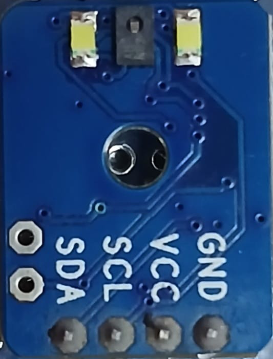
Pin Configuration and Descriptions

Pin Number Pin Name Description
1 VDD Power supply input (1.8V to 3.6V)
2 GND Ground
3 SDA I²C data line
4 SCL I²C clock line
5 INT Interrupt output (active low)
6 GPIO General-purpose input/output
7 NC Not connected (leave unconnected)

Usage Instructions

How to Use the AS7343 in a Circuit

  1. Power Supply: Connect the VDD pin to a stable power source (1.8V to 3.6V) and the GND pin to ground.
  2. I²C Communication: Connect the SDA and SCL pins to the corresponding I²C data and clock lines of your microcontroller. Use pull-up resistors (typically 4.7 kΩ) on both lines.
  3. Interrupt Pin: Optionally, connect the INT pin to a GPIO pin on your microcontroller to handle interrupts.
  4. GPIO Pin: The GPIO pin can be configured for additional functionality if required.
  5. Bypass Capacitor: Place a 0.1 µF decoupling capacitor close to the VDD pin to ensure stable operation.

Important Considerations and Best Practices

  • Ensure the sensor is not exposed to direct sunlight or high-intensity light sources during operation, as this may saturate the readings.
  • Use proper shielding and grounding techniques to minimize noise in the I²C communication lines.
  • Calibrate the sensor for your specific application to achieve accurate measurements.
  • Avoid placing the sensor near heat sources, as temperature variations can affect its performance.

Example Code for Arduino UNO

The following example demonstrates how to interface the AS7343 with an Arduino UNO using the I²C protocol. This code reads data from the sensor and prints the spectral channel values to the Serial Monitor.

#include <Wire.h>

// AS7343 I²C address
#define AS7343_I2C_ADDR 0x39

// Register addresses (example for enabling the sensor)
#define ENABLE_REG 0x80
#define ENABLE_POWER_ON 0x01
#define ENABLE_SPECTRAL_MEASUREMENT 0x02

void setup() {
  Wire.begin(); // Initialize I²C communication
  Serial.begin(9600); // Start Serial communication for debugging

  // Initialize the AS7343
  Wire.beginTransmission(AS7343_I2C_ADDR);
  Wire.write(ENABLE_REG); // Point to the enable register
  Wire.write(ENABLE_POWER_ON | ENABLE_SPECTRAL_MEASUREMENT); 
  // Enable power and spectral measurement
  Wire.endTransmission();

  Serial.println("AS7343 initialized.");
}

void loop() {
  // Example: Read spectral data (replace with actual register addresses)
  uint8_t spectralData[11]; // Array to store spectral channel data

  Wire.beginTransmission(AS7343_I2C_ADDR);
  Wire.write(0x90); // Example: Starting register for spectral data
  Wire.endTransmission();

  Wire.requestFrom(AS7343_I2C_ADDR, 11); // Request 11 bytes of data
  for (int i = 0; i < 11; i++) {
    if (Wire.available()) {
      spectralData[i] = Wire.read(); // Read each channel's data
    }
  }

  // Print spectral data to Serial Monitor
  Serial.println("Spectral Data:");
  for (int i = 0; i < 11; i++) {
    Serial.print("Channel ");
    Serial.print(i + 1);
    Serial.print(": ");
    Serial.println(spectralData[i]);
  }

  delay(1000); // Wait 1 second before the next reading
}

Troubleshooting and FAQs

Common Issues and Solutions

  1. No Response from the Sensor

    • Cause: Incorrect I²C address or wiring.
    • Solution: Verify the I²C address (default is 0x39) and ensure proper connections for SDA, SCL, VDD, and GND.
  2. Inaccurate Readings

    • Cause: Improper calibration or environmental interference.
    • Solution: Calibrate the sensor for your specific application and minimize external light interference.
  3. I²C Communication Errors

    • Cause: Missing pull-up resistors or excessive noise on the I²C lines.
    • Solution: Add 4.7 kΩ pull-up resistors to the SDA and SCL lines and ensure proper grounding.
  4. Interrupt Pin Not Working

    • Cause: Interrupts not enabled in the sensor configuration.
    • Solution: Check the sensor's configuration registers and enable interrupts if required.

FAQs

Q: Can the AS7343 measure UV or IR light?
A: The AS7343 is designed to measure light in the visible and near-infrared spectrum (350 nm to 1000 nm). It does not support UV light measurement.

Q: What is the maximum I²C clock speed supported?
A: The AS7343 supports I²C clock speeds up to 400 kHz (Fast Mode).

Q: How do I calibrate the sensor?
A: Calibration involves measuring known light sources and adjusting the sensor's output to match the expected values. Refer to the manufacturer's application notes for detailed calibration procedures.

Q: Can I use the AS7343 with a 5V microcontroller?
A: Yes, but you must use a level shifter to convert the 5V I²C signals to the sensor's operating voltage range (1.8V to 3.6V).