Cirkit Designer
Your all-in-one circuit design IDE
Home /
Component Documentation
How to Use GY-912: Examples, Pinouts, and Specs
Introduction
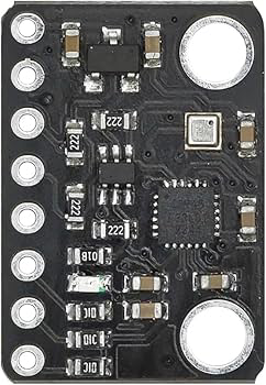
The GY-912 is a high-precision 9-axis motion tracking sensor module manufactured by OEM, with the part ID BMP388, ICM20948, 10DOF. This module integrates a 3-axis accelerometer, 3-axis gyroscope, and 3-axis magnetometer, making it ideal for applications requiring accurate orientation and motion detection. Additionally, it includes a BMP388 barometric pressure sensor for altitude measurement, enhancing its versatility.
Explore Projects Built with GY-912
Arduino Nano-Controlled Lighting System with Gesture and Sound Interaction
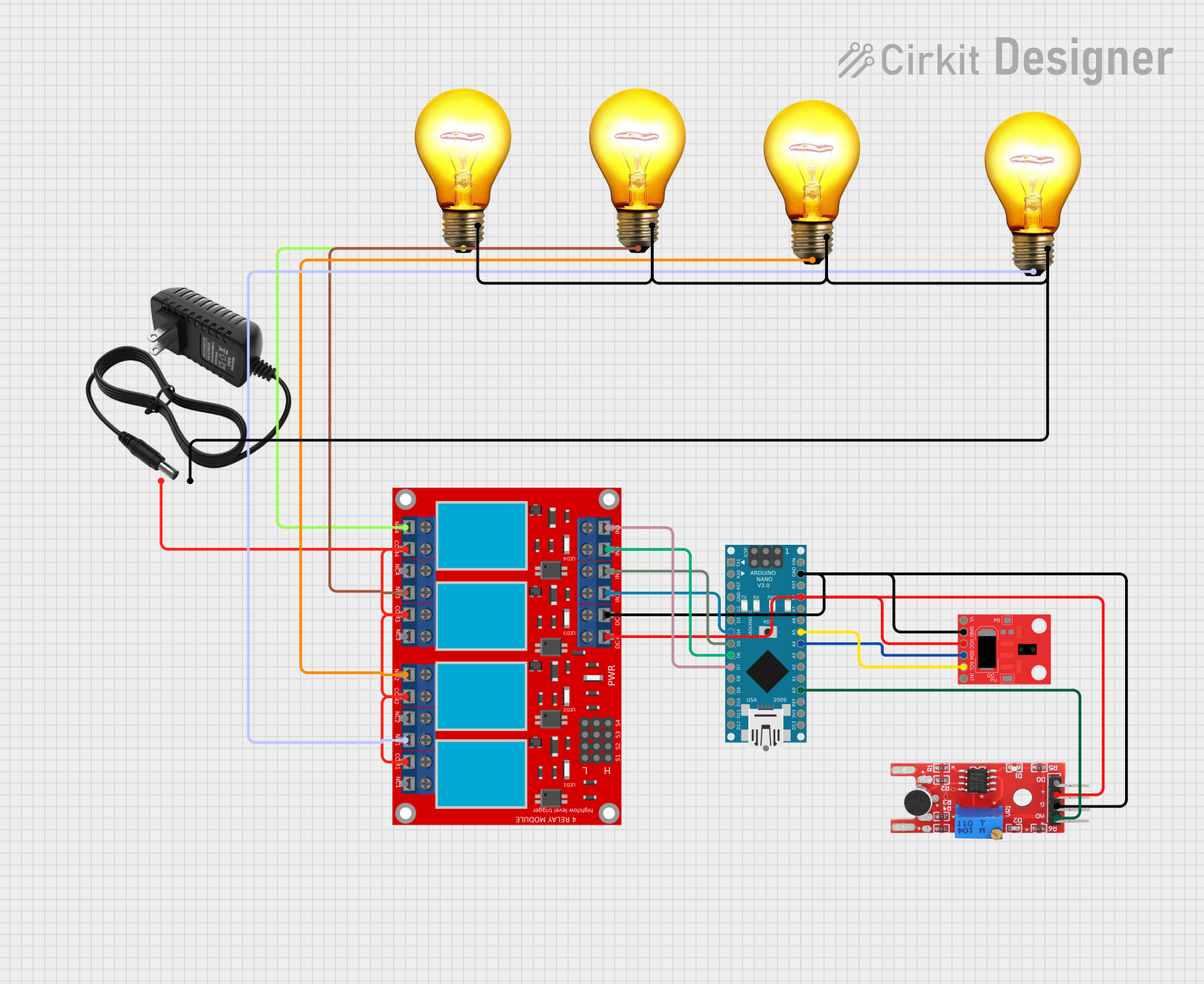
This circuit features an Arduino Nano microcontroller interfaced with an APDS-9960 RGB and Gesture Sensor for color and gesture detection, and a KY-038 microphone module for sound detection. The Arduino controls a 4-channel relay module, which in turn switches four AC bulbs on and off. The 12V power supply is used to power the relay module, and the bulbs are connected to the normally open (N.O.) contacts of the relays, allowing the Arduino to control the lighting based on sensor inputs.
Cellular-Enabled IoT Device with Real-Time Clock and Power Management

This circuit features a LilyGo-SIM7000G module for cellular communication and GPS functionality, interfaced with an RTC DS3231 for real-time clock capabilities. It includes voltage sensing through two voltage sensor modules, and uses an 8-channel opto-coupler for isolating different parts of the circuit. Power management is handled by a buck converter connected to a DC power source and batteries, with a fuse for protection and a rocker switch for on/off control. Additionally, there's an LED for indication purposes.
Multi-Channel Load Cell Measurement System with JYS60 Amplifiers and DAQ Integration

This is a multi-channel load cell measurement system with several JYS60 amplifiers connected to load cells for weight or force sensing. The amplified signals are directed to a DAQ system for data capture, and power is supplied through a barrel jack. Grounding is achieved via an AdaGator Side Black component.
Solar-Powered Environmental Monitoring Station with GSM Reporting

This is a solar-powered monitoring and control system with automatic power source selection, environmental sensing, and communication capabilities. It uses an ESP32 microcontroller to process inputs from gas, flame, and temperature sensors, and to manage outputs like an LCD display, LEDs, and a buzzer. The system can communicate via a SIM900A module and switch between solar and AC power sources using an ATS.
Explore Projects Built with GY-912
Arduino Nano-Controlled Lighting System with Gesture and Sound Interaction
This circuit features an Arduino Nano microcontroller interfaced with an APDS-9960 RGB and Gesture Sensor for color and gesture detection, and a KY-038 microphone module for sound detection. The Arduino controls a 4-channel relay module, which in turn switches four AC bulbs on and off. The 12V power supply is used to power the relay module, and the bulbs are connected to the normally open (N.O.) contacts of the relays, allowing the Arduino to control the lighting based on sensor inputs.
Cellular-Enabled IoT Device with Real-Time Clock and Power Management
This circuit features a LilyGo-SIM7000G module for cellular communication and GPS functionality, interfaced with an RTC DS3231 for real-time clock capabilities. It includes voltage sensing through two voltage sensor modules, and uses an 8-channel opto-coupler for isolating different parts of the circuit. Power management is handled by a buck converter connected to a DC power source and batteries, with a fuse for protection and a rocker switch for on/off control. Additionally, there's an LED for indication purposes.
Multi-Channel Load Cell Measurement System with JYS60 Amplifiers and DAQ Integration
This is a multi-channel load cell measurement system with several JYS60 amplifiers connected to load cells for weight or force sensing. The amplified signals are directed to a DAQ system for data capture, and power is supplied through a barrel jack. Grounding is achieved via an AdaGator Side Black component.
Solar-Powered Environmental Monitoring Station with GSM Reporting
This is a solar-powered monitoring and control system with automatic power source selection, environmental sensing, and communication capabilities. It uses an ESP32 microcontroller to process inputs from gas, flame, and temperature sensors, and to manage outputs like an LCD display, LEDs, and a buzzer. The system can communicate via a SIM900A module and switch between solar and AC power sources using an ATS.
Common Applications
- Robotics for motion tracking and navigation
- Drones for stabilization and flight control
- Wearable devices for activity monitoring
- Virtual reality (VR) and augmented reality (AR) systems
- IoT devices requiring environmental and motion sensing
Technical Specifications
Key Technical Details
| Parameter | Value |
|---|---|
| Manufacturer | OEM |
| Part ID | BMP388, ICM20948, 10DOF |
| Supply Voltage | 3.3V - 5V |
| Communication Interface | I2C, SPI |
| Accelerometer Range | ±2g, ±4g, ±8g, ±16g |
| Gyroscope Range | ±250, ±500, ±1000, ±2000 degrees/second |
| Magnetometer Range | ±4900 µT |
| Barometric Pressure Range | 300 hPa to 1250 hPa |
| Operating Temperature | -40°C to +85°C |
| Dimensions | 15mm x 10mm |
Pin Configuration
| Pin Name | Description |
|---|---|
| VCC | Power supply input (3.3V - 5V) |
| GND | Ground |
| SCL | I2C clock line |
| SDA | I2C data line |
| CS | Chip select for SPI communication |
| SDO | SPI data output |
| INT | Interrupt output |
Usage Instructions
How to Use the GY-912 in a Circuit
- Power Supply: Connect the VCC pin to a 3.3V or 5V power source and the GND pin to ground.
- Communication Interface:
- For I2C: Connect the SDA and SCL pins to the corresponding pins on your microcontroller.
- For SPI: Connect the CS, SDO, and SCL pins to the appropriate SPI pins on your microcontroller.
- Interrupt Pin: Optionally, connect the INT pin to a GPIO pin on your microcontroller to handle interrupts.
- Pull-Up Resistors: Ensure pull-up resistors (typically 4.7kΩ) are used on the SDA and SCL lines if not already present on the module.
Best Practices
- Use decoupling capacitors near the power supply pins to reduce noise.
- Keep the module away from strong magnetic fields to avoid interference with the magnetometer.
- Calibrate the accelerometer, gyroscope, and magnetometer for accurate readings.
- Use libraries or drivers compatible with the BMP388 and ICM20948 for easier integration.
Example Code for Arduino UNO
Below is an example of how to interface the GY-912 with an Arduino UNO using the I2C protocol:
#include <Wire.h>
#include <Adafruit_Sensor.h>
#include <Adafruit_ICM20948.h>
#include <Adafruit_BMP3XX.h>

// Create sensor objects
Adafruit_ICM20948 icm; // ICM20948 9-axis sensor
Adafruit_BMP3XX bmp;   // BMP388 barometric pressure sensor

void setup() {
  Serial.begin(115200);
  while (!Serial); // Wait for Serial Monitor to open

  // Initialize I2C communication
  if (!icm.begin_I2C()) {
    Serial.println("Failed to find ICM20948 sensor!");
    while (1);
  }
  Serial.println("ICM20948 initialized!");

  if (!bmp.begin_I2C()) {
    Serial.println("Failed to find BMP388 sensor!");
    while (1);
  }
  Serial.println("BMP388 initialized!");
}

void loop() {
  // Read accelerometer data
  sensors_event_t accel, gyro, mag;
  icm.getEvent(&accel, &gyro, &mag);

  Serial.print("Accel X: "); Serial.print(accel.acceleration.x); Serial.print(" m/s^2, ");
  Serial.print("Y: "); Serial.print(accel.acceleration.y); Serial.print(" m/s^2, ");
  Serial.print("Z: "); Serial.print(accel.acceleration.z); Serial.println(" m/s^2");

  // Read barometric pressure
  if (bmp.performReading()) {
    Serial.print("Pressure: "); Serial.print(bmp.pressure / 100.0); Serial.println(" hPa");
    Serial.print("Altitude: "); Serial.print(bmp.readAltitude(1013.25)); Serial.println(" m");
  } else {
    Serial.println("Failed to read BMP388 sensor!");
  }

  delay(1000); // Wait 1 second before next reading
}
Notes
- Install the
Adafruit_ICM20948andAdafruit_BMP3XXlibraries via the Arduino Library Manager before running the code. - Adjust the
bmp.readAltitude()function's sea-level pressure parameter (1013.25 hPa) based on your location for accurate altitude readings.
Troubleshooting and FAQs
Common Issues
No Sensor Detected:
- Ensure the module is powered correctly (check VCC and GND connections).
- Verify the I2C address matches the one used in your code (default is 0x68 for ICM20948).
- Check for loose or incorrect wiring.
Inaccurate Readings:
- Perform sensor calibration for the accelerometer, gyroscope, and magnetometer.
- Avoid placing the module near sources of magnetic interference.
Communication Errors:
- Ensure pull-up resistors are present on the I2C lines.
- Check that the correct communication protocol (I2C or SPI) is selected in your code.
Tips for Troubleshooting
- Use an I2C scanner sketch to confirm the module's I2C address.
- Test the module with a different microcontroller or power source to rule out hardware issues.
- Consult the datasheets for the BMP388 and ICM20948 for advanced debugging.
By following this documentation, you can effectively integrate the GY-912 module into your projects and troubleshoot common issues.