How to Use Buck Boost XL6009: Examples, Pinouts, and Specs
Introduction
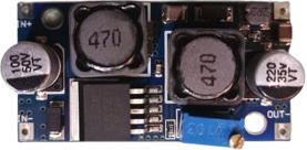
The Buck Boost XL6009 is a versatile DC-DC converter module capable of stepping up (boosting) or stepping down (bucking) input voltage levels to provide a stable and adjustable output voltage. It is based on the XL6009 regulator IC, which features high efficiency, fast switching frequency, and a wide input voltage range. This module is ideal for applications requiring voltage regulation, such as battery-powered devices, LED drivers, and portable electronics.
Explore Projects Built with Buck Boost XL6009


Explore Projects Built with Buck Boost XL6009
Common Applications and Use Cases
- Power supply for microcontrollers and development boards (e.g., Arduino, Raspberry Pi)
- Battery voltage regulation for lithium-ion or lead-acid batteries
- LED lighting systems
- Solar-powered devices
- DIY electronics projects requiring adjustable voltage levels
Technical Specifications
The following are the key technical details of the Buck Boost XL6009 module:
| Parameter | Specification |
|---|---|
| Input Voltage Range | 3V to 32V |
| Output Voltage Range | 5V to 35V (adjustable via potentiometer) |
| Maximum Output Current | 4A (with proper heat dissipation) |
| Efficiency | Up to 94% |
| Switching Frequency | 400 kHz |
| Operating Temperature | -40°C to +85°C |
| Dimensions | 43mm x 21mm x 14mm |
Pin Configuration and Descriptions
The module has four main pins for input and output connections:
| Pin Name | Description |
|---|---|
| VIN+ | Positive input voltage terminal (3V to 32V) |
| VIN- | Negative input voltage terminal (GND) |
| VOUT+ | Positive output voltage terminal (5V to 35V) |
| VOUT- | Negative output voltage terminal (GND) |
Usage Instructions
How to Use the Buck Boost XL6009 in a Circuit
Connect the Input Voltage:
- Connect the positive terminal of your power source to the
VIN+pin. - Connect the negative terminal of your power source to the
VIN-pin.
- Connect the positive terminal of your power source to the
Connect the Output Load:
- Connect the positive terminal of your load to the
VOUT+pin. - Connect the negative terminal of your load to the
VOUT-pin.
- Connect the positive terminal of your load to the
Adjust the Output Voltage:
- Use the onboard potentiometer to adjust the output voltage.
- Turn the potentiometer clockwise to increase the output voltage and counterclockwise to decrease it.
- Use a multimeter to measure the output voltage while adjusting.
Ensure Proper Heat Dissipation:
- For high current applications, attach a heatsink to the XL6009 IC to prevent overheating.
Important Considerations and Best Practices
- Input Voltage Range: Ensure the input voltage is within the specified range (3V to 32V). Exceeding this range may damage the module.
- Output Voltage Adjustment: Always measure the output voltage with a multimeter before connecting your load to avoid overvoltage damage.
- Current Limitations: The module can handle up to 4A, but proper heat dissipation is required for currents above 2A.
- Polarity Protection: The module does not have reverse polarity protection. Double-check your connections before powering it on.
Example: Using the XL6009 with an Arduino UNO
The Buck Boost XL6009 can be used to power an Arduino UNO by providing a stable 9V output. Below is an example setup:
- Connect a 5V power source (e.g., USB power bank) to the
VIN+andVIN-pins of the XL6009. - Adjust the output voltage to 9V using the potentiometer.
- Connect the
VOUT+pin to the Arduino'sVINpin and theVOUT-pin to the Arduino'sGNDpin.
Here is a simple Arduino code example to blink an LED, powered by the XL6009:
// Simple LED Blink Example
// This code assumes the Arduino UNO is powered by the XL6009 module
// with a stable 9V output connected to the Arduino's VIN pin.

const int ledPin = 13; // Built-in LED pin on Arduino UNO

void setup() {
  pinMode(ledPin, OUTPUT); // Set the LED pin as an output
}

void loop() {
  digitalWrite(ledPin, HIGH); // Turn the LED on
  delay(1000);                // Wait for 1 second
  digitalWrite(ledPin, LOW);  // Turn the LED off
  delay(1000);                // Wait for 1 second
}
Troubleshooting and FAQs
Common Issues and Solutions
No Output Voltage:
- Cause: Incorrect input connections or insufficient input voltage.
- Solution: Verify the input connections and ensure the input voltage is within the 3V to 32V range.
Output Voltage Not Adjustable:
- Cause: Faulty potentiometer or incorrect adjustment.
- Solution: Check the potentiometer for damage and ensure you are turning it in the correct direction.
Overheating:
- Cause: High current draw without proper heat dissipation.
- Solution: Attach a heatsink to the XL6009 IC and ensure adequate ventilation.
Load Not Powering On:
- Cause: Output voltage too low or too high for the load.
- Solution: Measure the output voltage with a multimeter and adjust it to match the load's requirements.
FAQs
Q: Can the XL6009 module be used with a solar panel?
A: Yes, the XL6009 is suitable for solar panel applications. Ensure the input voltage from the solar panel is within the module's range (3V to 32V).
Q: Is the XL6009 module safe for sensitive electronics?
A: Yes, but you should measure and adjust the output voltage carefully before connecting sensitive devices to avoid overvoltage damage.
Q: Can the module handle AC input?
A: No, the XL6009 is designed for DC input only. Use a rectifier circuit to convert AC to DC before connecting it to the module.