How to Use UEETEK L298N Dual H Bridge DC Stepper Motor Driver Module Controller Board for Arduino: Examples, Pinouts, and Specs
Introduction
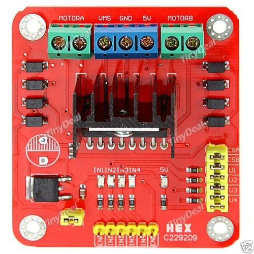
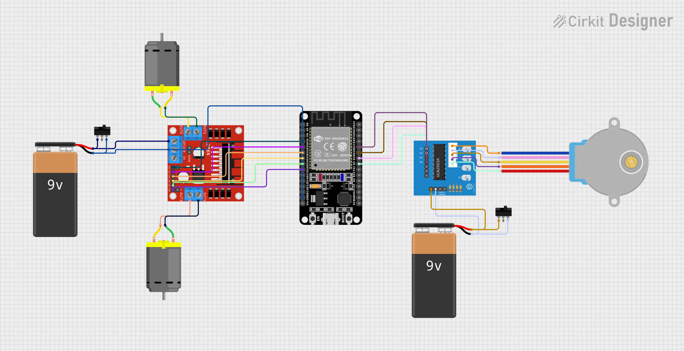
The UEETEK L298N Dual H Bridge Motor Driver is a versatile module designed for controlling the direction and speed of stepper motors or DC motors. It features a dual H-bridge, which allows for the independent control of two motors, making it ideal for robotics and automation projects. Compatible with Arduino and other microcontrollers, the L298N is widely used in DIY electronics due to its ease of use and functionality.
Explore Projects Built with UEETEK L298N Dual H Bridge DC Stepper Motor Driver Module Controller Board for Arduino
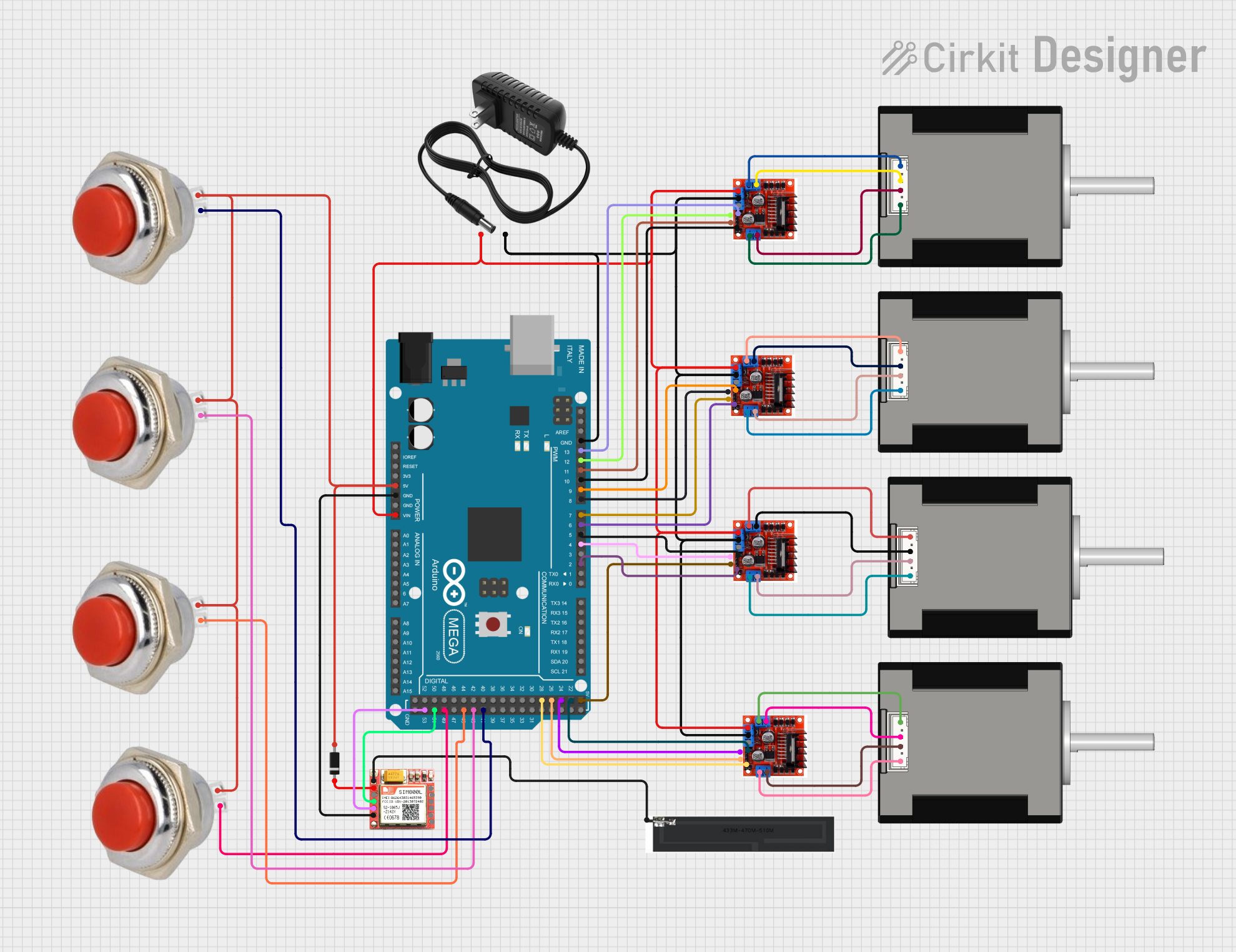
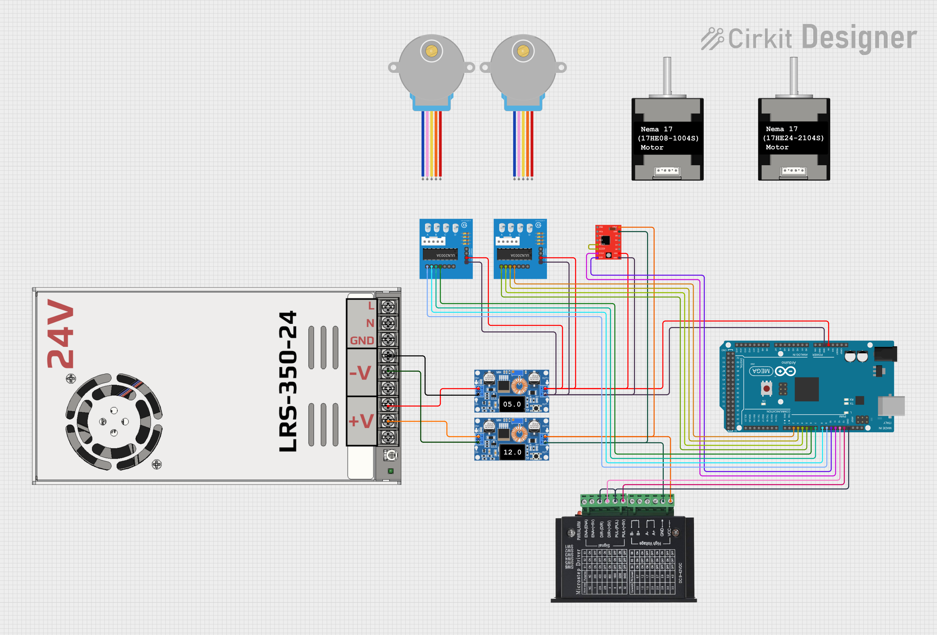
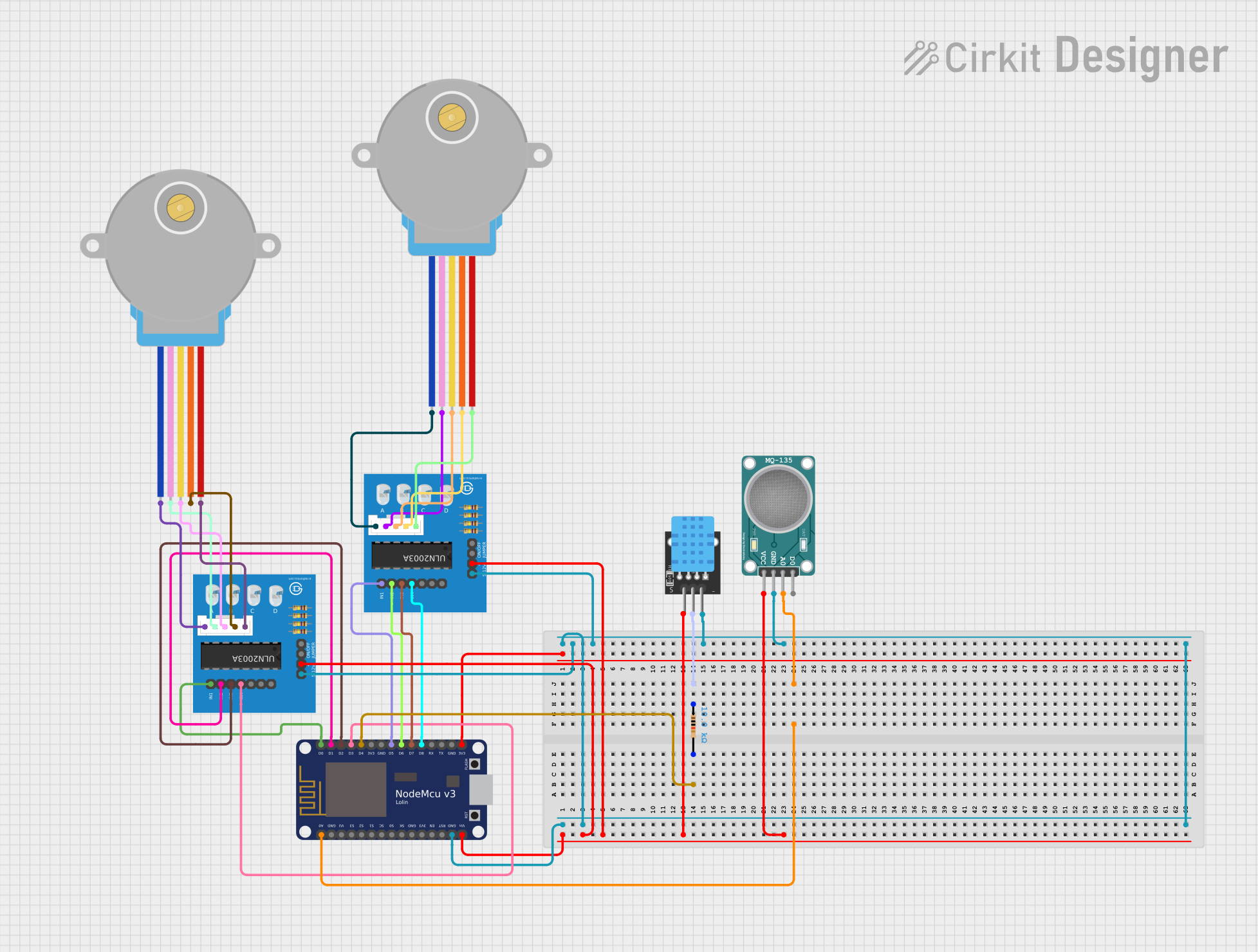
Explore Projects Built with UEETEK L298N Dual H Bridge DC Stepper Motor Driver Module Controller Board for Arduino
Common Applications and Use Cases
- Robotics
- CNC machines
- Automated guided vehicles
- Position and speed control systems
Technical Specifications
Key Technical Details
- Operating Voltage: 5V-35V
- Logic Voltage: 5V
- Continuous Current: 2A per channel or 4A max (with external power supply)
- Peak Current: Up to 3A per channel
- Power Consumption: 20W (max)
Pin Configuration and Descriptions
| Pin Number | Name | Description |
|---|---|---|
| 1 | IN1 | Input 1 for Motor A |
| 2 | IN2 | Input 2 for Motor A |
| 3 | IN3 | Input 1 for Motor B |
| 4 | IN4 | Input 2 for Motor B |
| 5 | ENA | Enable Motor A |
| 6 | ENB | Enable Motor B |
| 7 | +12V | Motor Power Supply (12V recommended) |
| 8 | GND | Ground |
| 9 | +5V | Logic Power Supply (if required) |
Usage Instructions
How to Use the Component in a Circuit
- Connect the motor to the L298N module's output terminals.
- Supply the logic voltage (5V) to the +5V pin if using the onboard 5V regulator.
- Connect the ground pin to the system ground.
- Apply the motor power supply to the +12V pin.
- Connect the input pins (IN1, IN2, IN3, IN4) to the digital outputs of the Arduino or microcontroller.
- Use the enable pins (ENA, ENB) to control the speed of the motors via PWM signals.
Important Considerations and Best Practices
- Ensure the power supply voltage and current do not exceed the module's ratings.
- Use external power when driving motors that require more than 2A.
- Always connect the grounds of the L298N module and the microcontroller.
- Use flyback diodes if driving inductive loads to protect against voltage spikes.
Example Code for Arduino UNO
// Define motor control pins
#define IN1 2
#define IN2 3
#define IN3 4
#define IN4 5
#define ENA 9
#define ENB 10

void setup() {
  // Set motor control pins as outputs
  pinMode(IN1, OUTPUT);
  pinMode(IN2, OUTPUT);
  pinMode(IN3, OUTPUT);
  pinMode(IN4, OUTPUT);
  pinMode(ENA, OUTPUT);
  pinMode(ENB, OUTPUT);
}

void loop() {
  // Motor A forward
  digitalWrite(IN1, HIGH);
  digitalWrite(IN2, LOW);
  analogWrite(ENA, 200); // Speed control with PWM signal

  // Motor B forward
  digitalWrite(IN3, HIGH);
  digitalWrite(IN4, LOW);
  analogWrite(ENB, 200); // Speed control with PWM signal

  delay(2000); // Run motors for 2 seconds

  // Stop motors
  digitalWrite(IN1, LOW);
  digitalWrite(IN2, LOW);
  digitalWrite(IN3, LOW);
  digitalWrite(IN4, LOW);
  analogWrite(ENA, 0);
  analogWrite(ENB, 0);

  delay(1000); // Wait for 1 second
}
Troubleshooting and FAQs
Common Issues
- Motor not running: Check power supply and connections. Ensure the input pins are receiving the correct signals.
- Motor stalling or weak: Verify that the power supply can deliver sufficient current. Check for overheating.
- Inconsistent motor speed: Ensure PWM signals are stable and that the enable pins are connected properly.
Solutions and Tips for Troubleshooting
- Double-check wiring and solder joints for any loose connections.
- Use a multimeter to verify the voltage levels at the motor and input pins.
- If using PWM for speed control, ensure the frequency is appropriate for the motor.
FAQs
Q: Can I control a single stepper motor with this module? A: Yes, the L298N can control a single stepper motor by using both H-bridges in a coordinated manner.
Q: What is the maximum voltage and current the module can handle? A: The maximum recommended motor voltage is 35V, and the continuous current is 2A per channel.
Q: Can I use this module without an external power supply? A: It is possible for small motors with low current requirements, but an external power supply is recommended for most applications.
Q: How do I reverse the motor direction? A: To reverse the motor direction, swap the HIGH and LOW states of the input pins controlling the motor.
Remember, this documentation is a starting point. Always consult the datasheet and manufacturer's resources for the most detailed and accurate information.