
How to Use Mini AC-DC 110V-230V to 5V 700mA Module: Examples, Pinouts, and Specs
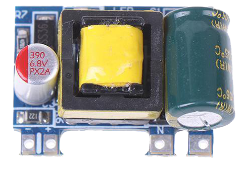
 Design with Mini AC-DC 110V-230V to 5V 700mA Module in Cirkit Designer
Introduction
The Mini AC-DC 110V-230V to 5V 700mA Module by PermanentFly is a compact and efficient power supply module designed to convert high AC voltage (110V-230V) into a stable 5V DC output. With a maximum current output of 700mA, this module is ideal for powering low-voltage electronic devices, such as microcontrollers, sensors, and small IoT devices. Its small size and high efficiency make it a popular choice for embedded systems and DIY electronics projects.
Explore Projects Built with Mini AC-DC 110V-230V to 5V 700mA Module
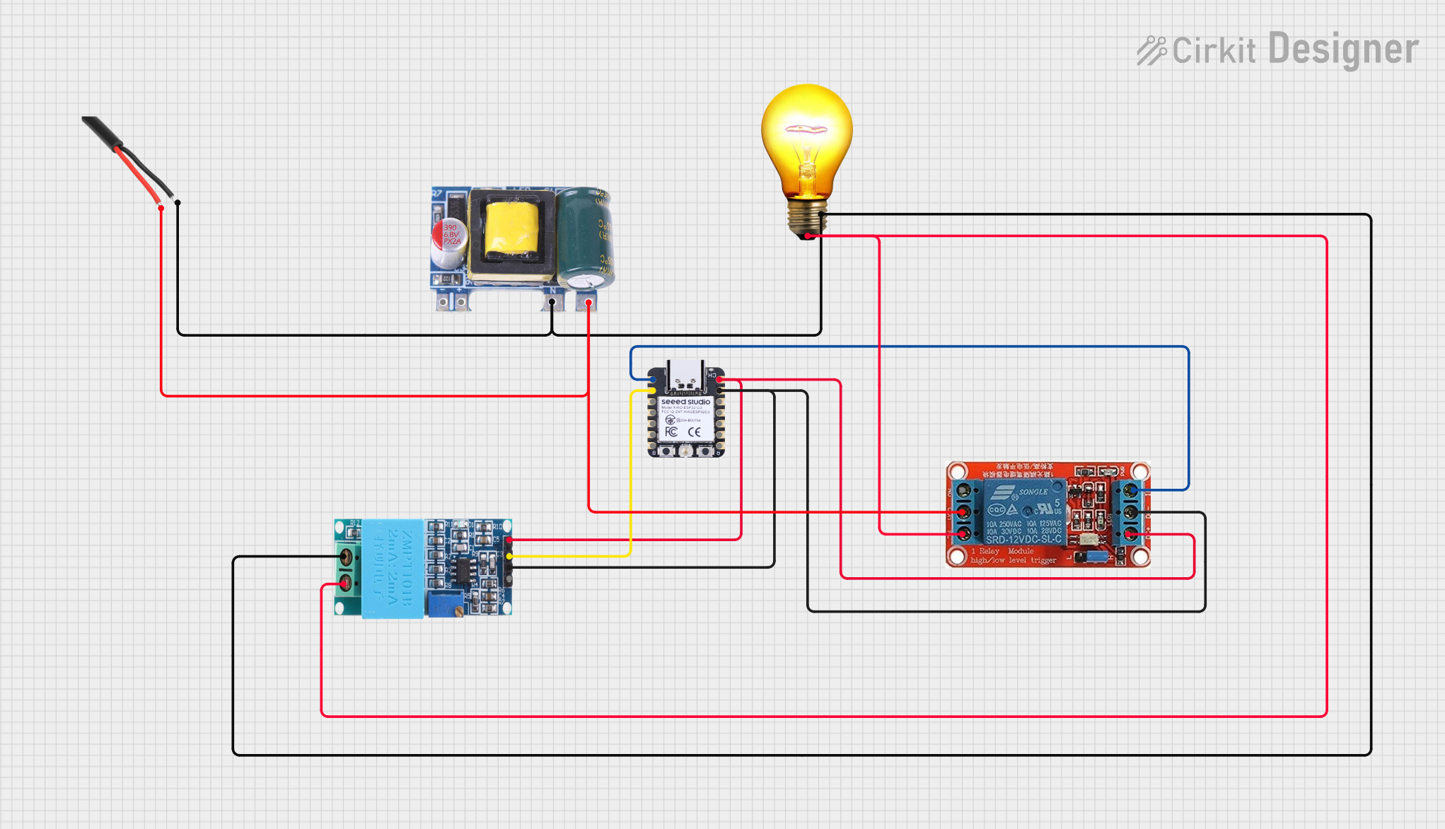 Open Project in Cirkit Designer
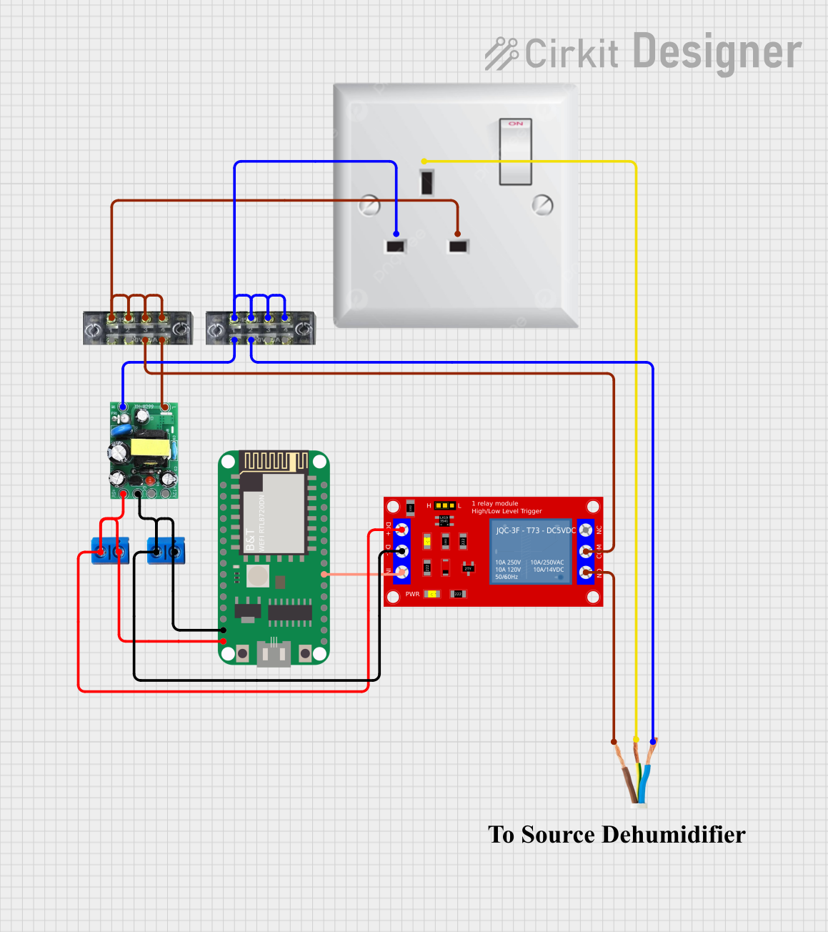 Open Project in Cirkit Designer
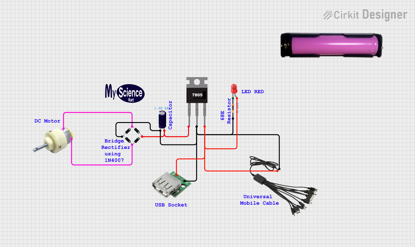 Open Project in Cirkit Designer
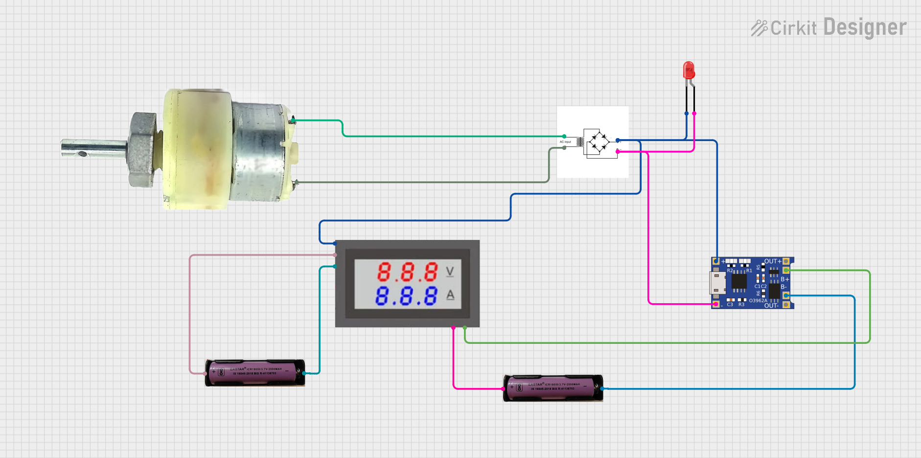 Open Project in Cirkit Designer
Explore Projects Built with Mini AC-DC 110V-230V to 5V 700mA Module
Open Project in Cirkit DesignerOpen Project in Cirkit DesignerOpen Project in Cirkit DesignerOpen Project in Cirkit DesignerCommon Applications
- Powering microcontrollers (e.g., Arduino, ESP8266, ESP32, Raspberry Pi Pico)
- IoT devices and smart home applications
- Low-power sensors and modules
- DIY electronics and prototyping
- Replacing bulky linear power supplies in compact designs
Technical Specifications
Key Technical Details
| Parameter | Value |
|---|---|
| Input Voltage Range | 110V-230V AC |
| Output Voltage | 5V DC |
| Maximum Output Current | 700mA |
| Power Output | 3.5W |
| Efficiency | ≥ 80% |
| Operating Temperature | -25°C to +70°C |
| Dimensions | ~33mm x 20mm x 15mm |
| Isolation Voltage | 3000V AC |
| Manufacturer | PermanentFly |
Pin Configuration and Descriptions
| Pin Name | Description |
|---|---|
| AC IN1 | AC input terminal 1 (connect to live wire) |
| AC IN2 | AC input terminal 2 (connect to neutral wire) |
| DC OUT+ | Positive DC output (5V) |
| DC OUT- | Negative DC output (GND) |
Usage Instructions
How to Use the Module in a Circuit
- Safety First: Ensure the module is handled with care, as it operates with high AC voltage. Always disconnect power before making any connections.
- Connect AC Input:
- Connect the AC IN1 pin to the live wire of the AC mains.
- Connect the AC IN2 pin to the neutral wire of the AC mains.
- Use proper insulation and secure connections to avoid electrical hazards.
- Connect DC Output:
- Connect the DC OUT+ pin to the positive terminal of your load (e.g., microcontroller VCC).
- Connect the DC OUT- pin to the ground terminal of your load (e.g., microcontroller GND).
- Verify Connections: Double-check all connections before powering the module.
- Power On: Once all connections are secure, power on the AC mains. The module will provide a stable 5V DC output.
Important Considerations and Best Practices
- Isolation: Ensure proper isolation between the AC and DC sides to prevent electrical shocks.
- Load Requirements: Do not exceed the maximum output current of 700mA to avoid overheating or damage.
- Heat Dissipation: If the module operates near its maximum load, ensure adequate ventilation to dissipate heat.
- Testing: Use a multimeter to verify the output voltage before connecting sensitive devices.
- Arduino Compatibility: This module can directly power an Arduino UNO or similar boards via their 5V and GND pins.
Example: Using the Module with an Arduino UNO
Below is an example of how to connect the module to an Arduino UNO and blink an LED:
Circuit Connections
- Connect DC OUT+ to the Arduino's 5V pin.
- Connect DC OUT- to the Arduino's GND pin.
- Connect an LED to pin 13 of the Arduino with a 220-ohm resistor in series.
Arduino Code
// Simple LED Blink Example
// This code blinks an LED connected to pin 13 of the Arduino UNO.

void setup() {
  pinMode(13, OUTPUT); // Set pin 13 as an output pin
}

void loop() {
  digitalWrite(13, HIGH); // Turn the LED on
  delay(1000);            // Wait for 1 second
  digitalWrite(13, LOW);  // Turn the LED off
  delay(1000);            // Wait for 1 second
}
Troubleshooting and FAQs
Common Issues and Solutions
| Issue | Possible Cause | Solution |
|---|---|---|
| No output voltage | Incorrect AC input connection | Verify AC IN1 and AC IN2 connections. |
| Output voltage is unstable | Exceeding maximum load current | Reduce the load to ≤ 700mA. |
| Module overheating | Prolonged operation at maximum load | Improve ventilation or reduce the load. |
| Arduino not powering on | Loose or incorrect DC output connection | Check DC OUT+ and DC OUT- connections. |
FAQs
Can this module power a Raspberry Pi?
No, the module's maximum current output (700mA) is insufficient for most Raspberry Pi models, which typically require at least 2.5A.Is the module safe to use with AC mains?
Yes, but proper insulation and secure connections are essential to ensure safety.Can I use this module outdoors?
The module is not weatherproof. Use it only in dry, indoor environments or enclose it in a weatherproof case.What happens if I exceed the maximum load?
Exceeding 700mA may cause the module to overheat, shut down, or become permanently damaged.
This concludes the documentation for the Mini AC-DC 110V-230V to 5V 700mA Module by PermanentFly. Always prioritize safety and follow best practices when working with high-voltage components.