Cirkit Designer
Your all-in-one circuit design IDE
Home /
Component Documentation
How to Use ESP32-S3-Pico: Examples, Pinouts, and Specs
Introduction
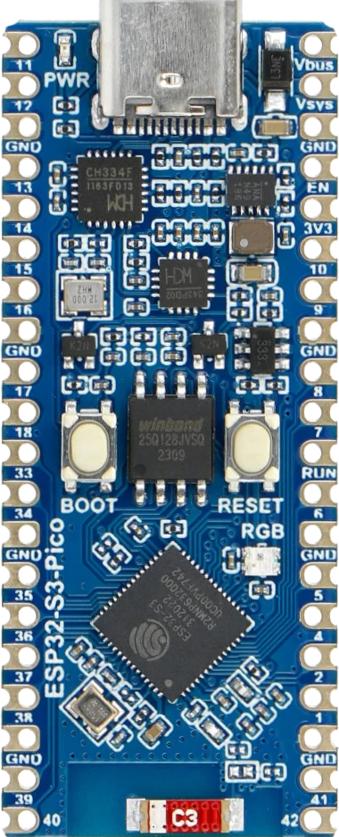
The ESP32-S3-Pico is a compact microcontroller module developed by Waveshare. It is based on the ESP32-S3 chip, which features dual-core processing, Wi-Fi, and Bluetooth connectivity. This versatile module is designed for a wide range of IoT and embedded applications, offering a rich set of I/O options and powerful processing capabilities.
Explore Projects Built with ESP32-S3-Pico
ESP32-S3 Based Automated Watering System with Ultrasonic Sensing and Data Logging

This circuit features an ESP32-S3 microcontroller connected to various peripherals including an HC-SR04 ultrasonic sensor, a water flow sensor, an OLED display, a DS3231 real-time clock (RTC), an SD card module, a water pump, a two-channel relay, and a valve solenoid. The ESP32-S3 manages sensor readings, data logging, and controls the water pump and valve via the relay based on sensor inputs. The circuit is designed for monitoring and controlling water flow, likely in an automated irrigation or fluid management system.
ESP32-S3 Based Vibration Detection System with TFT Display and Power Backup

This circuit features an ESP32-S3 microcontroller connected to various peripherals including an ADXL355 accelerometer, an SW-420 vibration sensor, a buzzer module, and an ILI9341 TFT display. The ESP32-S3 manages sensor inputs and provides output to the display and buzzer. Power management is handled by a 12V to 5V step-down converter, and a UPS ensures uninterrupted power supply, with a rocker switch to control the power flow.
Raspberry Pi Pico and ESP32 Wi-Fi Controlled Sensor Interface

This circuit integrates a Raspberry Pi Pico and an ESP32 Wroom Dev Kit, interconnected through various GPIO pins and resistors, to enable communication and control between the two microcontrollers. The ESP32 is powered by a 3.3V supply and shares ground with the Raspberry Pi Pico, while specific GPIO pins are used for data exchange. The provided code sketches for the Raspberry Pi Pico suggest a framework for further development of the system's functionality.
ESP32-S3 Based Environmental Monitoring and Control System with Data Logging

This circuit features an ESP32-S3 microcontroller interfaced with various sensors and modules, including a DHT22 temperature and humidity sensor, an HC-SR04 ultrasonic sensor, an SGP41 VOC and NOx sensor, and an Adafruit INA260 current and power sensor. The ESP32-S3 also controls a DC motor via a relay and communicates with an SD card and an OLED display. An Arduino UNO is used to read inputs from a rotary encoder, and a step-down buck converter is used to regulate voltage from a 12V battery to power the components.
Explore Projects Built with ESP32-S3-Pico
ESP32-S3 Based Automated Watering System with Ultrasonic Sensing and Data Logging
This circuit features an ESP32-S3 microcontroller connected to various peripherals including an HC-SR04 ultrasonic sensor, a water flow sensor, an OLED display, a DS3231 real-time clock (RTC), an SD card module, a water pump, a two-channel relay, and a valve solenoid. The ESP32-S3 manages sensor readings, data logging, and controls the water pump and valve via the relay based on sensor inputs. The circuit is designed for monitoring and controlling water flow, likely in an automated irrigation or fluid management system.
ESP32-S3 Based Vibration Detection System with TFT Display and Power Backup
This circuit features an ESP32-S3 microcontroller connected to various peripherals including an ADXL355 accelerometer, an SW-420 vibration sensor, a buzzer module, and an ILI9341 TFT display. The ESP32-S3 manages sensor inputs and provides output to the display and buzzer. Power management is handled by a 12V to 5V step-down converter, and a UPS ensures uninterrupted power supply, with a rocker switch to control the power flow.
Raspberry Pi Pico and ESP32 Wi-Fi Controlled Sensor Interface
This circuit integrates a Raspberry Pi Pico and an ESP32 Wroom Dev Kit, interconnected through various GPIO pins and resistors, to enable communication and control between the two microcontrollers. The ESP32 is powered by a 3.3V supply and shares ground with the Raspberry Pi Pico, while specific GPIO pins are used for data exchange. The provided code sketches for the Raspberry Pi Pico suggest a framework for further development of the system's functionality.
ESP32-S3 Based Environmental Monitoring and Control System with Data Logging
This circuit features an ESP32-S3 microcontroller interfaced with various sensors and modules, including a DHT22 temperature and humidity sensor, an HC-SR04 ultrasonic sensor, an SGP41 VOC and NOx sensor, and an Adafruit INA260 current and power sensor. The ESP32-S3 also controls a DC motor via a relay and communicates with an SD card and an OLED display. An Arduino UNO is used to read inputs from a rotary encoder, and a step-down buck converter is used to regulate voltage from a 12V battery to power the components.
Common Applications and Use Cases
- IoT Devices: Smart home systems, environmental monitoring, and industrial IoT.
- Wearable Technology: Fitness trackers, smartwatches, and health monitoring devices.
- Embedded Systems: Robotics, automation, and control systems.
- Wireless Communication: Wi-Fi and Bluetooth-enabled devices for data transmission and remote control.
Technical Specifications
Key Technical Details
| Parameter | Value |
|---|---|
| Chipset | ESP32-S3 |
| CPU | Dual-core Xtensa LX7 |
| Clock Speed | Up to 240 MHz |
| Flash Memory | 4 MB |
| SRAM | 512 KB |
| Wi-Fi | 802.11 b/g/n |
| Bluetooth | Bluetooth 5.0 (LE) |
| Operating Voltage | 3.3V |
| I/O Voltage | 3.3V |
| GPIO Pins | 26 |
| ADC Channels | 12-bit, 20 channels |
| DAC Channels | 2 channels |
| Communication | UART, SPI, I2C, I2S, CAN, Ethernet MAC |
| Power Consumption | Ultra-low power consumption in deep sleep |
Pin Configuration and Descriptions
| Pin Number | Pin Name | Description |
|---|---|---|
| 1 | GND | Ground |
| 2 | 3V3 | 3.3V Power Supply |
| 3 | EN | Enable (Active High) |
| 4 | IO0 | GPIO0, Boot Mode Select |
| 5 | IO1 | GPIO1, UART0 TXD |
| 6 | IO2 | GPIO2, ADC2 Channel 2 |
| 7 | IO3 | GPIO3, UART0 RXD |
| 8 | IO4 | GPIO4, ADC2 Channel 0 |
| 9 | IO5 | GPIO5, ADC2 Channel 1 |
| 10 | IO6 | GPIO6, SPI Flash SCK |
| 11 | IO7 | GPIO7, SPI Flash SD0 |
| 12 | IO8 | GPIO8, SPI Flash SD1 |
| 13 | IO9 | GPIO9, SPI Flash SD2 |
| 14 | IO10 | GPIO10, SPI Flash SD3 |
| 15 | IO11 | GPIO11, SPI Flash CMD |
| 16 | IO12 | GPIO12, ADC2 Channel 5 |
| 17 | IO13 | GPIO13, ADC2 Channel 4 |
| 18 | IO14 | GPIO14, ADC2 Channel 6 |
| 19 | IO15 | GPIO15, ADC2 Channel 3 |
| 20 | IO16 | GPIO16, UART2 TXD |
| 21 | IO17 | GPIO17, UART2 RXD |
| 22 | IO18 | GPIO18, I2C SCL |
| 23 | IO19 | GPIO19, I2C SDA |
| 24 | IO20 | GPIO20, SPI MOSI |
| 25 | IO21 | GPIO21, SPI MISO |
| 26 | IO22 | GPIO22, SPI SCK |
| 27 | IO23 | GPIO23, SPI CS |
Usage Instructions
How to Use the Component in a Circuit
- Power Supply: Connect the 3V3 pin to a 3.3V power source and the GND pin to ground.
- Enable Pin: Connect the EN pin to a high logic level (3.3V) to enable the module.
- GPIO Pins: Use the GPIO pins for digital input/output operations. Configure them as needed in your code.
- Communication Interfaces: Utilize UART, SPI, I2C, and other communication interfaces for connecting peripherals.
- Wi-Fi and Bluetooth: Use the built-in Wi-Fi and Bluetooth capabilities for wireless communication.
Important Considerations and Best Practices
- Voltage Levels: Ensure all I/O pins operate at 3.3V to avoid damaging the module.
- Power Consumption: Utilize deep sleep modes to minimize power consumption in battery-powered applications.
- Antenna Placement: For optimal wireless performance, place the module away from metal objects and other sources of interference.
- Firmware Updates: Regularly update the firmware to benefit from the latest features and security patches.
Example Code for Arduino UNO
#include <WiFi.h>

// Replace with your network credentials
const char* ssid = "your_SSID";
const char* password = "your_PASSWORD";

void setup() {
  // Initialize serial communication at 115200 baud rate
  Serial.begin(115200);

  // Connect to Wi-Fi network
  WiFi.begin(ssid, password);

  // Wait for connection
  while (WiFi.status() != WL_CONNECTED) {
    delay(1000);
    Serial.println("Connecting to WiFi...");
  }

  // Print the IP address
  Serial.println("Connected to WiFi");
  Serial.print("IP Address: ");
  Serial.println(WiFi.localIP());
}

void loop() {
  // Add your main code here, to run repeatedly
}
Troubleshooting and FAQs
Common Issues Users Might Face
Wi-Fi Connection Issues:
- Solution: Ensure the SSID and password are correct. Check for interference from other devices.
Module Not Powering On:
- Solution: Verify the power supply voltage is 3.3V. Check connections to the EN pin.
GPIO Pins Not Responding:
- Solution: Ensure the pins are correctly configured in the code. Check for short circuits or incorrect wiring.
High Power Consumption:
- Solution: Utilize deep sleep modes and optimize code to reduce power usage.
Solutions and Tips for Troubleshooting
- Check Connections: Ensure all connections are secure and correctly oriented.
- Use Serial Monitor: Utilize the serial monitor for debugging and monitoring the module's status.
- Update Firmware: Keep the module's firmware up to date to avoid known issues and benefit from improvements.
- Consult Documentation: Refer to the official Waveshare documentation and community forums for additional support.
By following this documentation, users can effectively integrate the ESP32-S3-Pico into their projects, leveraging its powerful features for a wide range of applications.