How to Use GARMIN LYCOMING ENGINE SENSOR WIRING: Examples, Pinouts, and Specs
Introduction
The GARMIN Lycoming Engine Sensor Wiring is a specialized wiring harness designed to connect sensors in Lycoming aircraft engines to Garmin avionics systems. This component ensures reliable and accurate data transmission, enabling precise monitoring of engine performance. It is engineered to meet the demanding requirements of aviation environments, providing durability, compatibility, and ease of installation.
Explore Projects Built with GARMIN LYCOMING ENGINE SENSOR WIRING


Explore Projects Built with GARMIN LYCOMING ENGINE SENSOR WIRING
Common Applications and Use Cases
- Connecting engine sensors (e.g., temperature, pressure, RPM) to Garmin avionics systems.
- Monitoring critical engine parameters in Lycoming aircraft engines.
- Supporting real-time data acquisition for flight performance and safety.
- Used in general aviation aircraft equipped with Garmin avionics and Lycoming engines.
Technical Specifications
The GARMIN Lycoming Engine Sensor Wiring is built to aviation-grade standards, ensuring high reliability and performance. Below are the key technical details:
Key Technical Details
- Manufacturer: Garmin
- Part ID: ENGINE SENSOR WIRING
- Compatibility: Lycoming aircraft engines and Garmin avionics systems.
- Operating Voltage: 12V to 28V DC (dependent on aircraft electrical system).
- Temperature Range: -40°C to +85°C (-40°F to +185°F).
- Connector Type: Aviation-grade multi-pin connectors.
- Cable Length: Varies by model (typically 1.5m to 3m).
- Shielding: EMI/RFI shielded for noise immunity.
- Material: High-temperature, flame-retardant insulation.
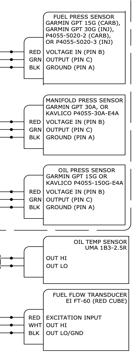
Pin Configuration and Descriptions
The wiring harness includes multiple connectors for interfacing with various engine sensors and the Garmin avionics system. Below is a typical pinout configuration:
Connector A (Engine Sensor Side)
| Pin | Signal | Description |
|---|---|---|
| 1 | Oil Pressure Sensor | Transmits oil pressure data |
| 2 | Oil Temperature Sensor | Transmits oil temperature data |
| 3 | Cylinder Head Temp (CHT) | Transmits cylinder head temperature data |
| 4 | Exhaust Gas Temp (EGT) | Transmits exhaust gas temperature data |
| 5 | RPM Sensor | Transmits engine RPM data |
| 6 | Ground | Common ground connection |
Connector B (Garmin Avionics Side)
| Pin | Signal | Description |
|---|---|---|
| 1 | Power Supply (+12V/28V) | Supplies power to sensors |
| 2 | Data Bus (CAN High) | CAN bus high signal for data transfer |
| 3 | Data Bus (CAN Low) | CAN bus low signal for data transfer |
| 4 | Ground | Common ground connection |
| 5 | Shield | EMI/RFI shielding |
Usage Instructions
How to Use the Component in a Circuit
- Identify the Sensors: Determine the sensors installed on the Lycoming engine (e.g., oil pressure, temperature, RPM).
- Connect the Harness:
- Attach Connector A to the corresponding engine sensors. Ensure each pin is connected to the correct sensor as per the pinout table.
- Attach Connector B to the Garmin avionics system.
- Secure the Wiring:
- Use aviation-grade cable ties or clamps to secure the wiring harness along the engine and airframe.
- Ensure the harness is routed away from high-temperature or moving parts.
- Power On the System:
- Turn on the aircraft's electrical system and Garmin avionics.
- Verify that the sensors are transmitting data correctly to the avionics display.
Important Considerations and Best Practices
- Compatibility: Ensure the wiring harness is compatible with your specific Lycoming engine model and Garmin avionics system.
- Installation: Follow FAA-approved installation procedures and guidelines for aviation wiring.
- Testing: After installation, perform a thorough system test to verify data accuracy and connectivity.
- Maintenance: Regularly inspect the wiring harness for wear, damage, or loose connections.
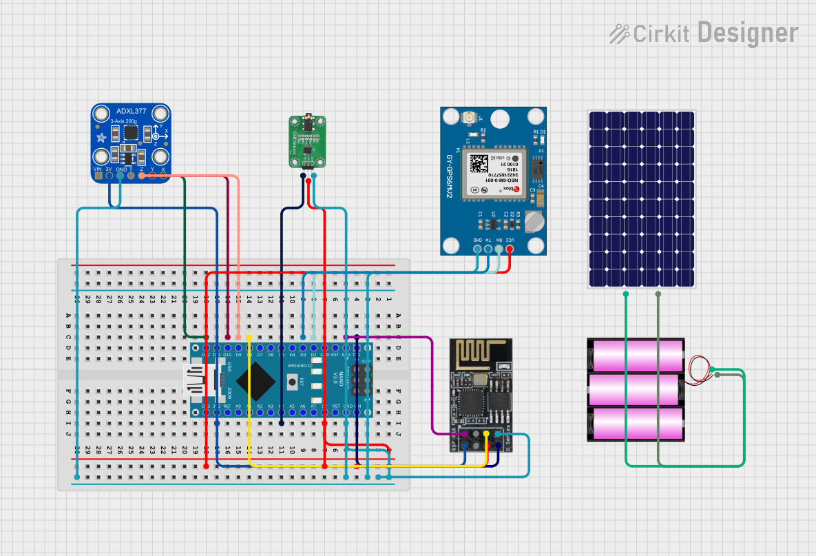
Example Code for Arduino Integration
While this component is primarily designed for aviation systems, it can be interfaced with an Arduino for testing or simulation purposes. Below is an example code snippet to read sensor data using an Arduino:
// Example code to simulate reading sensor data from the GARMIN Lycoming Engine Sensor Wiring
// This code assumes analog sensors connected to Arduino analog pins A0 to A3

const int oilPressurePin = A0;  // Pin for oil pressure sensor
const int oilTempPin = A1;      // Pin for oil temperature sensor
const int chtPin = A2;          // Pin for cylinder head temperature sensor
const int egtPin = A3;          // Pin for exhaust gas temperature sensor

void setup() {
  Serial.begin(9600);  // Initialize serial communication
  Serial.println("Engine Sensor Data Simulation");
}

void loop() {
  // Read sensor values (simulated as analog inputs)
  int oilPressure = analogRead(oilPressurePin);
  int oilTemp = analogRead(oilTempPin);
  int cht = analogRead(chtPin);
  int egt = analogRead(egtPin);

  // Print sensor values to the serial monitor
  Serial.print("Oil Pressure: ");
  Serial.println(oilPressure);
  Serial.print("Oil Temperature: ");
  Serial.println(oilTemp);
  Serial.print("CHT: ");
  Serial.println(cht);
  Serial.print("EGT: ");
  Serial.println(egt);

  delay(1000);  // Delay for 1 second
}
Troubleshooting and FAQs
Common Issues Users Might Face
No Data Displayed on Avionics:
- Cause: Loose or incorrect connections.
- Solution: Verify all connections using the pinout table. Ensure connectors are securely attached.
Intermittent Data Loss:
- Cause: EMI/RFI interference or damaged wiring.
- Solution: Check the shielding and routing of the wiring harness. Replace damaged sections.
Incorrect Sensor Readings:
- Cause: Faulty sensors or calibration issues.
- Solution: Test each sensor individually. Replace or recalibrate as needed.
Harness Overheating:
- Cause: Proximity to high-temperature engine components.
- Solution: Re-route the harness away from heat sources. Use heat-resistant insulation if necessary.
Solutions and Tips for Troubleshooting
- Use a multimeter to check continuity and voltage levels across the wiring harness.
- Refer to the Garmin and Lycoming documentation for specific sensor calibration procedures.
- Ensure the aircraft's electrical system is functioning correctly and providing stable power.
By following this documentation, users can effectively install, use, and troubleshoot the GARMIN Lycoming Engine Sensor Wiring for optimal engine performance monitoring.