
How to Use RX - RP4TD: Examples, Pinouts, and Specs
 Design with RX - RP4TD in Cirkit Designer
Introduction
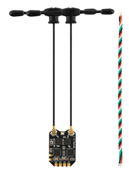
The RX - RP4TD is a high-performance receiver module designed for wireless communication. It is commonly used in remote control systems, data transmission applications, and other wireless communication setups. This module operates at specific frequencies and is capable of demodulating signals received from a compatible transmitter. Its compact design and reliable performance make it a popular choice for hobbyists and professionals alike.
Explore Projects Built with RX - RP4TD
 Open Project in Cirkit Designer
 Open Project in Cirkit Designer
 Open Project in Cirkit Designer
 Open Project in Cirkit Designer
Explore Projects Built with RX - RP4TD
Open Project in Cirkit DesignerOpen Project in Cirkit DesignerOpen Project in Cirkit DesignerOpen Project in Cirkit DesignerCommon Applications
- Remote control systems (e.g., RC cars, drones, and home automation)
- Wireless data transmission
- Internet of Things (IoT) devices
- Wireless sensor networks
- Industrial automation systems
Technical Specifications
The RX - RP4TD module is designed to provide reliable wireless communication with the following key specifications:
| Parameter | Value |
|---|---|
| Operating Frequency | 315 MHz / 433 MHz (varies by model) |
| Operating Voltage | 3.3V - 5V |
| Current Consumption | ≤ 5 mA |
| Sensitivity | -105 dBm |
| Modulation Type | ASK (Amplitude Shift Keying) |
| Data Rate | 2 kbps - 10 kbps |
| Operating Temperature | -20°C to +70°C |
| Dimensions | 30 mm x 14 mm x 7 mm |
Pin Configuration and Descriptions
The RX - RP4TD module typically has 4 pins, as described in the table below:
| Pin | Name | Description |
|---|---|---|
| 1 | VCC | Power supply pin. Connect to a 3.3V or 5V DC source. |
| 2 | DATA | Data output pin. Outputs the demodulated signal received from the transmitter. |
| 3 | GND | Ground pin. Connect to the ground of the power supply. |
| 4 | ANT | Antenna pin. Connect to an external antenna for better signal reception. |
Usage Instructions
How to Use the RX - RP4TD in a Circuit
- Power Supply: Connect the VCC pin to a 3.3V or 5V DC power source and the GND pin to the ground.
- Antenna Connection: Attach a suitable antenna to the ANT pin to improve signal reception. A simple wire of appropriate length (quarter wavelength of the operating frequency) can be used as an antenna.
- Data Output: Connect the DATA pin to a microcontroller or other processing unit to read the demodulated signal.
- Pairing with a Transmitter: Ensure the transmitter module operates at the same frequency as the RX - RP4TD for proper communication.
Important Considerations
- Antenna Design: The performance of the RX - RP4TD heavily depends on the quality and placement of the antenna. Ensure the antenna is not obstructed by metal objects or placed near sources of interference.
- Power Supply Stability: Use a stable power supply to avoid noise and ensure reliable operation.
- Signal Decoding: The data output from the module may require additional decoding, depending on the protocol used by the transmitter.
Example: Connecting RX - RP4TD to an Arduino UNO
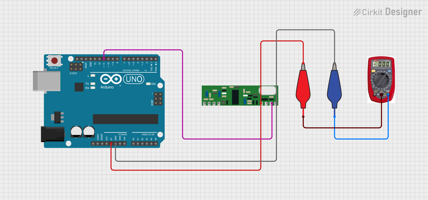
Below is an example of how to connect the RX - RP4TD to an Arduino UNO and read data from the module.
Circuit Connections
- Connect the VCC pin of the RX - RP4TD to the 5V pin on the Arduino.
- Connect the GND pin of the RX - RP4TD to the GND pin on the Arduino.
- Connect the DATA pin of the RX - RP4TD to digital pin 2 on the Arduino.
- Attach an antenna to the ANT pin of the RX - RP4TD.
Arduino Code
// RX - RP4TD Receiver Module Example Code
// This code reads data from the RX - RP4TD module and prints it to the Serial Monitor.

#define DATA_PIN 2  // Define the pin connected to the DATA pin of RX - RP4TD

void setup() {
  pinMode(DATA_PIN, INPUT);  // Set the DATA pin as input
  Serial.begin(9600);       // Initialize serial communication at 9600 baud
}

void loop() {
  int receivedData = digitalRead(DATA_PIN);  // Read the data from the RX - RP4TD
  Serial.println(receivedData);             // Print the received data to the Serial Monitor
  delay(100);                               // Add a small delay for stability
}
Notes:
- The above code assumes the transmitter is sending simple digital signals. For more complex protocols, additional decoding logic may be required.
- Ensure the transmitter and receiver are operating at the same frequency.
Troubleshooting and FAQs
Common Issues and Solutions
No Signal Received
- Cause: Incorrect frequency pairing between the transmitter and receiver.
- Solution: Verify that both modules are operating at the same frequency (e.g., 433 MHz).
Poor Signal Reception
- Cause: Improper antenna design or placement.
- Solution: Use a properly designed antenna and ensure it is placed away from interference sources.
Unstable Data Output
- Cause: Noisy power supply or interference.
- Solution: Use a decoupling capacitor (e.g., 0.1 µF) across the VCC and GND pins to stabilize the power supply.
Data Not Decoded Properly
- Cause: Incompatible protocol or missing decoding logic.
- Solution: Check the protocol used by the transmitter and implement the required decoding logic in your microcontroller.
FAQs
Q1: Can the RX - RP4TD work with any transmitter module?
A1: No, the transmitter must operate at the same frequency and use the same modulation type (ASK) for compatibility.
Q2: What type of antenna should I use?
A2: A simple wire antenna with a length of approximately 17 cm (for 433 MHz) or 23.8 cm (for 315 MHz) works well.
Q3: Can I use the RX - RP4TD with a 3.3V microcontroller?
A3: Yes, the RX - RP4TD supports an operating voltage range of 3.3V to 5V, making it compatible with 3.3V systems.
Q4: What is the maximum range of the RX - RP4TD?
A4: The range depends on factors such as antenna design, environmental conditions, and transmitter power. Typically, it can achieve up to 100 meters in open spaces.