How to Use to scale DPDT Latching Relay: Examples, Pinouts, and Specs
Introduction
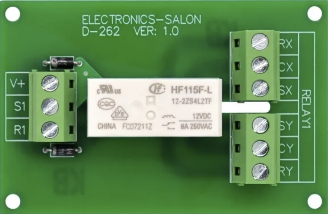
The Electronics Salon MD-D262/12V is a Double Pole Double Throw (DPDT) latching relay designed for efficient and reliable switching in electronic circuits. This relay features two sets of contacts, enabling it to control two independent circuits simultaneously. Its latching mechanism allows the relay to maintain its state (ON or OFF) even after the control signal is removed, making it ideal for applications requiring persistent states without continuous power consumption.
Explore Projects Built with to scale DPDT Latching Relay


Explore Projects Built with to scale DPDT Latching Relay
Common Applications and Use Cases
- Home automation systems
- Industrial control panels
- Audio signal routing
- Power management in battery-operated devices
- Memory circuits for maintaining states during power loss
Technical Specifications
Key Technical Details
| Parameter | Value |
|---|---|
| Manufacturer | Electronics Salon |
| Part Number | MD-D262/12V |
| Relay Type | DPDT (Double Pole Double Throw) |
| Coil Voltage | 12V DC |
| Coil Resistance | 400 Ω |
| Contact Rating | 10A @ 250V AC / 10A @ 30V DC |
| Contact Material | Silver Alloy |
| Switching Mechanism | Latching (Bistable) |
| Dimensions | 28mm x 12.5mm x 15mm |
| Operating Temperature | -40°C to +85°C |
| Mounting Type | PCB Mount |
Pin Configuration and Descriptions
The MD-D262/12V relay has a total of 8 pins. The pin configuration is as follows:
| Pin Number | Description |
|---|---|
| 1 | Coil Terminal A (Set) |
| 2 | Coil Terminal B (Reset) |
| 3 | Common Terminal for Pole 1 |
| 4 | Normally Closed (NC) Contact for Pole 1 |
| 5 | Normally Open (NO) Contact for Pole 1 |
| 6 | Common Terminal for Pole 2 |
| 7 | Normally Closed (NC) Contact for Pole 2 |
| 8 | Normally Open (NO) Contact for Pole 2 |
Usage Instructions
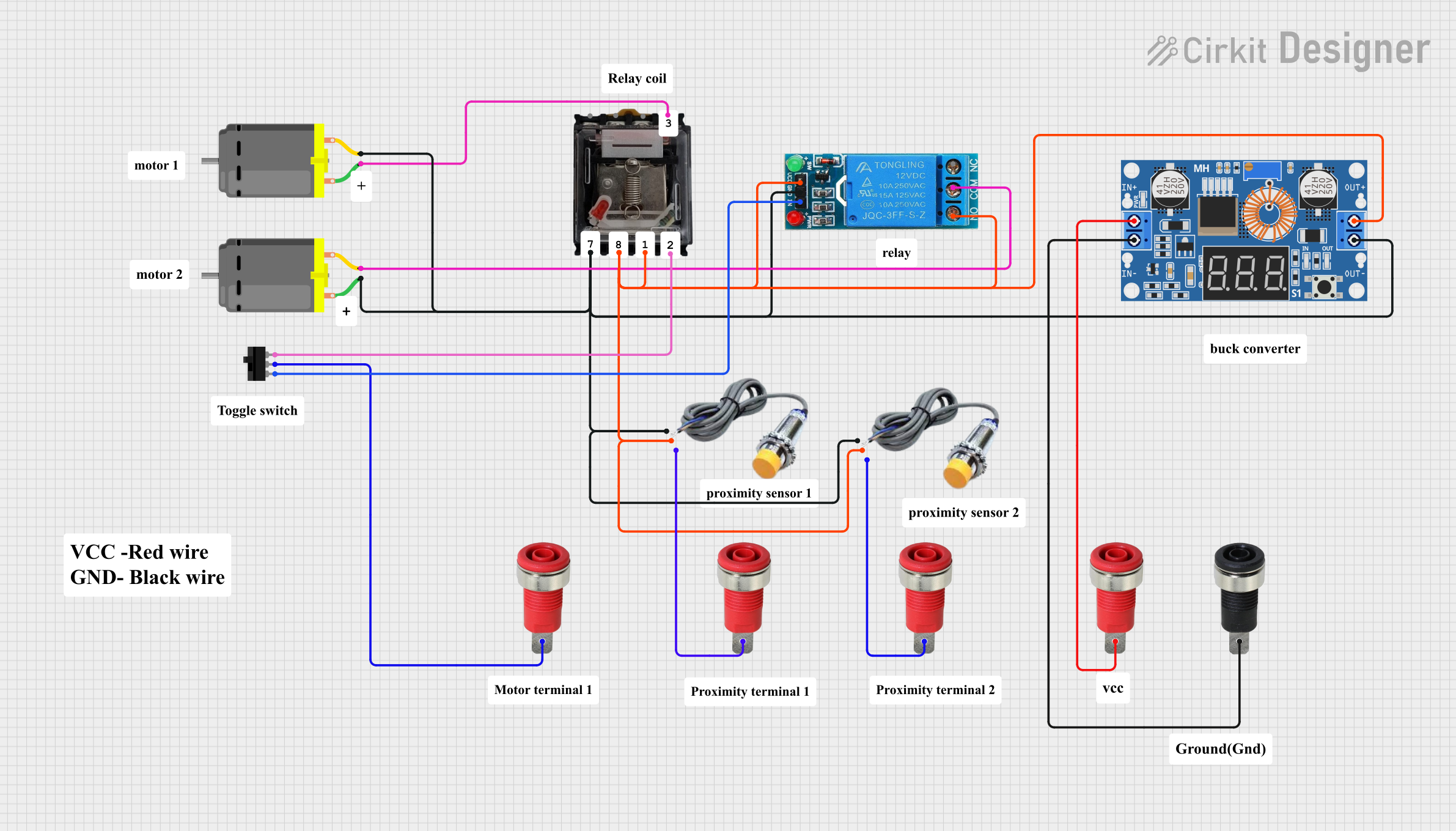
How to Use the Component in a Circuit
- Power the Relay Coil: Connect a 12V DC power source to the coil terminals (Pin 1 and Pin 2). Apply a momentary pulse to Pin 1 (Set) to activate the relay, or to Pin 2 (Reset) to deactivate it.
- Connect the Load: Wire the devices or circuits you want to control to the relay's contact terminals:
- Use Pin 3 (Common for Pole 1) with Pin 4 (NC) or Pin 5 (NO) for the first circuit.
- Use Pin 6 (Common for Pole 2) with Pin 7 (NC) or Pin 8 (NO) for the second circuit.
- Control the Relay: Use a microcontroller, switch, or other control circuit to send the required pulse to the coil terminals.
Important Considerations and Best Practices
- Momentary Pulses: Ensure that the control signal to the coil is a short pulse (not continuous) to avoid overheating the coil.
- Flyback Diode: Add a flyback diode across the coil terminals to protect the circuit from voltage spikes caused by the relay's inductive load.
- Contact Ratings: Do not exceed the relay's contact ratings (10A @ 250V AC or 10A @ 30V DC) to prevent damage.
- Polarity: Observe correct polarity when connecting the coil terminals to avoid malfunction.
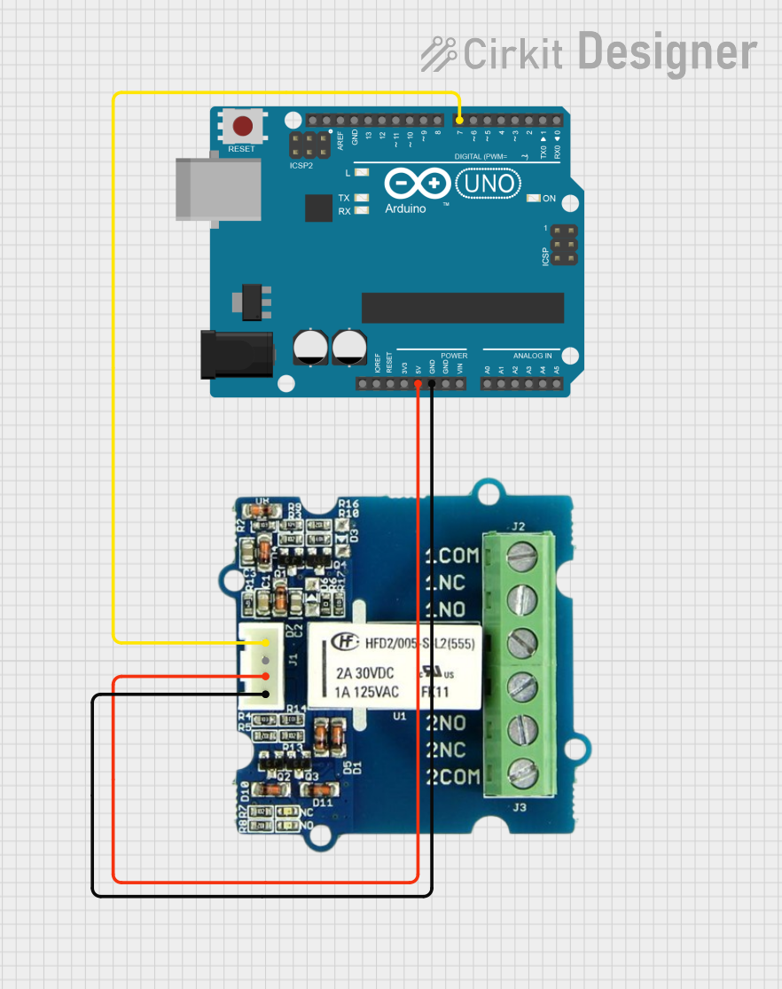
Example: Using the Relay with an Arduino UNO
Below is an example of how to control the MD-D262/12V relay using an Arduino UNO:
// Define the Arduino pins connected to the relay's coil terminals
const int setPin = 7;  // Pin connected to Coil Terminal A (Set)
const int resetPin = 8; // Pin connected to Coil Terminal B (Reset)

void setup() {
  // Set the relay control pins as outputs
  pinMode(setPin, OUTPUT);
  pinMode(resetPin, OUTPUT);

  // Initialize the relay in the OFF state
  digitalWrite(setPin, LOW);
  digitalWrite(resetPin, LOW);
}

void loop() {
  // Example: Turn the relay ON
  digitalWrite(setPin, HIGH);  // Send a pulse to the Set pin
  delay(100);                  // Wait for 100ms
  digitalWrite(setPin, LOW);   // Turn off the Set pin

  delay(5000);                 // Wait for 5 seconds

  // Example: Turn the relay OFF
  digitalWrite(resetPin, HIGH); // Send a pulse to the Reset pin
  delay(100);                   // Wait for 100ms
  digitalWrite(resetPin, LOW);  // Turn off the Reset pin

  delay(5000);                  // Wait for 5 seconds
}
Notes:
- Replace
setPinandresetPinwith the actual pins connected to the relay in your circuit. - Ensure the Arduino's output pins can provide sufficient current to drive the relay or use a transistor driver circuit if needed.
Troubleshooting and FAQs
Common Issues and Solutions
Relay Does Not Switch
- Cause: Insufficient voltage or current to the coil.
- Solution: Verify that the coil is receiving 12V DC and sufficient current. Check for loose connections.
Relay Stays in One State
- Cause: Control signal is not a momentary pulse.
- Solution: Ensure the control signal is a short pulse (e.g., 100ms). Continuous signals may cause the relay to overheat or malfunction.
Voltage Spikes in the Circuit
- Cause: Inductive kickback from the relay coil.
- Solution: Install a flyback diode (e.g., 1N4007) across the coil terminals to suppress voltage spikes.
Contacts Overheat or Fail
- Cause: Exceeding the contact's current or voltage rating.
- Solution: Ensure the load connected to the relay does not exceed 10A @ 250V AC or 10A @ 30V DC.
FAQs
Q: Can I use this relay with a 5V control signal?
A: No, the MD-D262/12V requires a 12V DC control signal to operate. Use a transistor or relay driver circuit to step up the control voltage if needed.
Q: Does the relay consume power continuously?
A: No, the latching mechanism ensures the relay retains its state without continuous power to the coil.
Q: Can I use this relay for AC loads?
A: Yes, the relay supports AC loads up to 10A @ 250V AC. Ensure proper insulation and safety precautions when working with high voltages.
Q: How do I reset the relay to its default state?
A: Apply a momentary pulse to the Reset pin (Coil Terminal B) to switch the relay to its default state.
This concludes the documentation for the Electronics Salon MD-D262/12V DPDT Latching Relay.