How to Use Diode 1N4148W: Examples, Pinouts, and Specs
Introduction
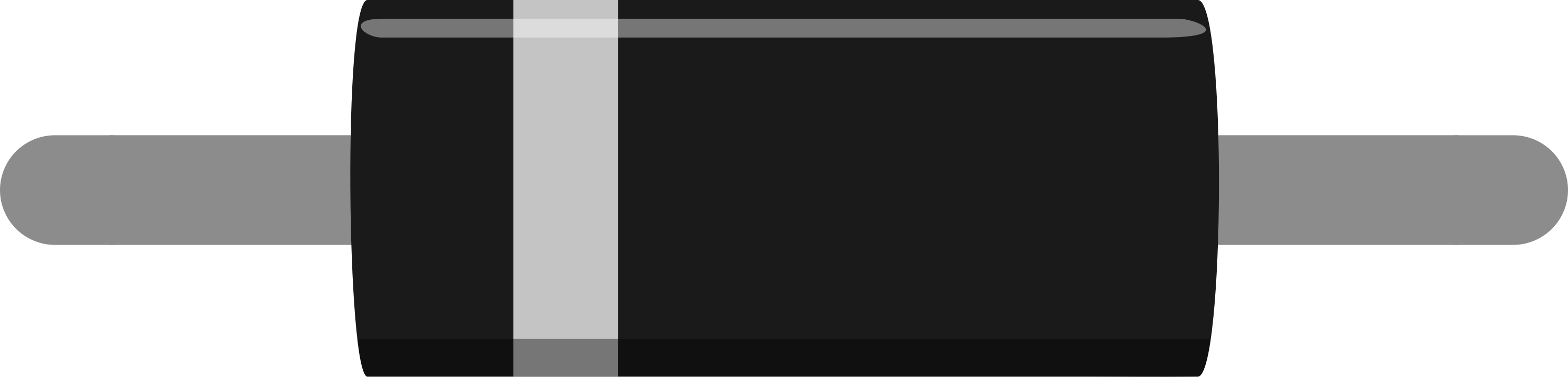
The 1N4148W is a small-signal switching diode renowned for its fast switching speed and low forward voltage drop. It is widely used in electronic circuits for rectification, signal processing, and protection purposes. Its compact SOD-123 package makes it suitable for surface-mount applications, and its reliability ensures consistent performance in a variety of environments.
Explore Projects Built with Diode 1N4148W
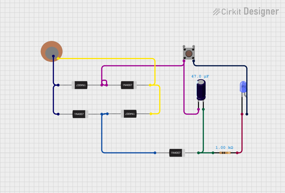
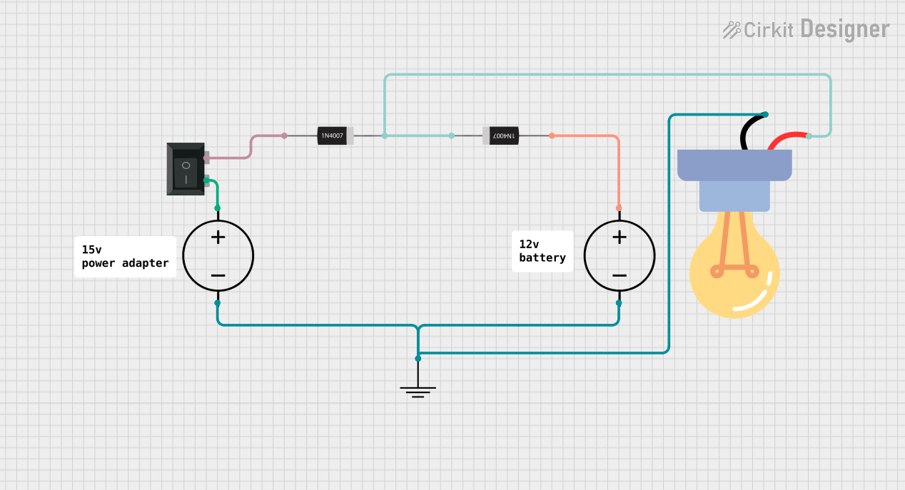
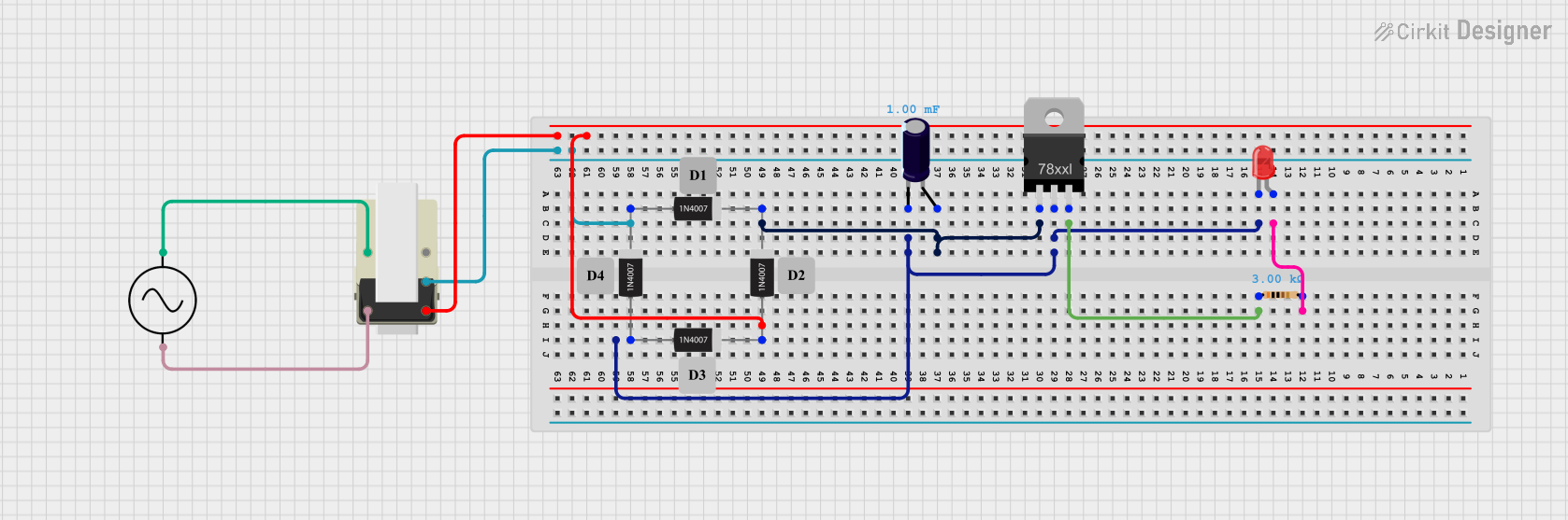

Explore Projects Built with Diode 1N4148W
Common Applications
- High-speed switching circuits
- Signal rectification and demodulation
- Voltage clamping and protection
- Logic circuits and waveform shaping
- RF and microwave applications
Technical Specifications
Below are the key technical details of the 1N4148W diode:
| Parameter | Value |
|---|---|
| Package Type | SOD-123 |
| Maximum Reverse Voltage (VR) | 100 V |
| Forward Voltage (VF) | 1.0 V (at 10 mA) |
| Maximum Average Rectified Current (IF(AV)) | 300 mA |
| Peak Forward Surge Current (IFSM) | 2 A (for 1 µs pulse) |
| Reverse Recovery Time (trr) | 4 ns (typical) |
| Power Dissipation (PD) | 400 mW |
| Operating Temperature Range | -65°C to +150°C |
Pin Configuration
The 1N4148W diode has two terminals:
| Pin | Name | Description |
|---|---|---|
| 1 | Anode | Positive terminal; current flows into this pin. |
| 2 | Cathode | Negative terminal; current flows out of this pin. |
The cathode is typically marked with a band on the diode's body.
Usage Instructions
How to Use the 1N4148W in a Circuit
- Identify the Polarity: Ensure the anode and cathode are correctly oriented in the circuit. The cathode is marked with a band.
- Connect in Series: For rectification or signal processing, connect the diode in series with the load or signal path.
- Observe Voltage and Current Ratings: Ensure the applied voltage does not exceed the maximum reverse voltage (100 V) and the forward current stays within the rated limits (300 mA average).
- Use in High-Speed Applications: The 1N4148W is ideal for circuits requiring fast switching due to its 4 ns reverse recovery time.
Important Considerations
- Thermal Management: Ensure adequate heat dissipation to prevent the diode from exceeding its maximum power dissipation of 400 mW.
- Reverse Voltage Protection: Avoid applying reverse voltages beyond the rated 100 V to prevent breakdown.
- Parasitic Capacitance: In high-frequency circuits, consider the diode's junction capacitance, which may affect performance.
Example: Using the 1N4148W with an Arduino UNO
The 1N4148W can be used for signal rectification or protection in Arduino circuits. Below is an example of using the diode for voltage clamping to protect an input pin:
// Example: Protecting an Arduino input pin using the 1N4148W diode

const int inputPin = 2;  // Define the input pin
void setup() {
  pinMode(inputPin, INPUT);  // Set the pin as input
  Serial.begin(9600);       // Initialize serial communication
}

void loop() {
  int sensorValue = digitalRead(inputPin);  // Read the input pin
  Serial.println(sensorValue);             // Print the value to the Serial Monitor
  delay(100);                              // Small delay for stability
}

/*
Circuit Description:
- Connect the cathode of the 1N4148W to the Arduino input pin (e.g., pin 2).
- Connect the anode to ground. This configuration clamps any voltage spikes
  above the forward voltage (approximately 1 V) to protect the input pin.
*/
Troubleshooting and FAQs
Common Issues
Diode Overheating:
- Cause: Exceeding the maximum forward current or power dissipation.
- Solution: Use a series resistor to limit current or improve heat dissipation.
Incorrect Polarity:
- Cause: Reversing the anode and cathode connections.
- Solution: Verify the orientation of the diode before powering the circuit.
No Signal Rectification:
- Cause: Insufficient forward voltage or incorrect circuit design.
- Solution: Ensure the input signal exceeds the diode's forward voltage (1 V).
FAQs
Q1: Can the 1N4148W handle AC signals?
A1: Yes, the 1N4148W can rectify AC signals when used in a rectifier circuit. Ensure the peak voltage does not exceed the diode's reverse voltage rating.
Q2: What is the difference between the 1N4148 and 1N4148W?
A2: The 1N4148W is the surface-mount version of the 1N4148, which is typically available in a through-hole package. Both have similar electrical characteristics.
Q3: Can I use the 1N4148W for power rectification?
A3: No, the 1N4148W is designed for small-signal applications and cannot handle high currents required for power rectification.
Q4: How do I test if the diode is functional?
A4: Use a multimeter in diode mode. A functional diode will show a forward voltage drop (~0.6-1 V) when the probes are connected correctly and no conduction in reverse.
By following this documentation, you can effectively integrate the 1N4148W diode into your electronic projects.