
How to Use ESP32-C6-LCD-1.3: Examples, Pinouts, and Specs
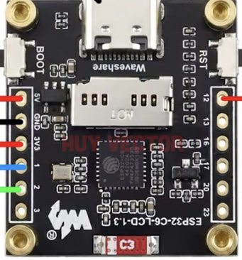
 Design with ESP32-C6-LCD-1.3 in Cirkit Designer
Introduction
The ESP32-C6-LCD-1.3 is a compact display module manufactured by Waveshare (Part ID: ESP32). It features an ESP32-C6 microcontroller with integrated Wi-Fi 6 and Bluetooth 5.0 capabilities, making it ideal for IoT and embedded applications. The module includes a 1.3-inch LCD screen for visual output, enabling developers to create interactive and visually rich projects. Its small form factor and versatile connectivity options make it suitable for smart home devices, wearable electronics, industrial automation, and more.
Explore Projects Built with ESP32-C6-LCD-1.3
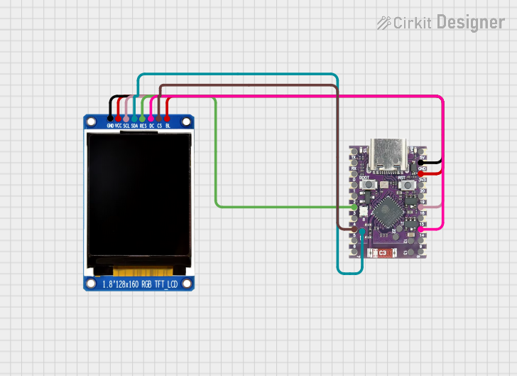 Open Project in Cirkit Designer
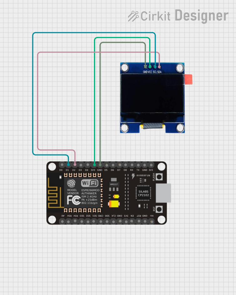 Open Project in Cirkit Designer
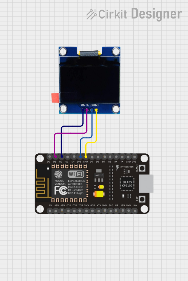 Open Project in Cirkit Designer
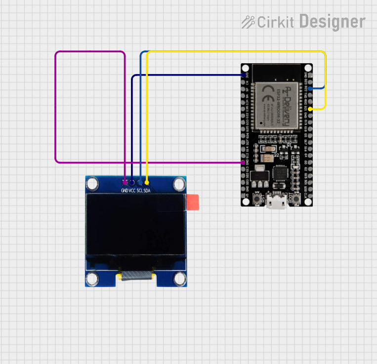 Open Project in Cirkit Designer
Explore Projects Built with ESP32-C6-LCD-1.3
Open Project in Cirkit DesignerOpen Project in Cirkit DesignerOpen Project in Cirkit DesignerOpen Project in Cirkit DesignerCommon Applications:
- IoT devices with real-time data visualization
- Smart home control panels
- Wearable electronics with graphical interfaces
- Industrial monitoring systems
- Educational and prototyping projects
Technical Specifications
Key Technical Details:
| Parameter | Specification |
|---|---|
| Microcontroller | ESP32-C6 |
| Wireless Connectivity | Wi-Fi 6, Bluetooth 5.0 |
| Display | 1.3-inch TFT LCD, 240x240 resolution |
| Operating Voltage | 3.3V |
| Power Supply | 5V via USB-C or external source |
| GPIO Pins | 14 (configurable for various functions) |
| Flash Memory | 4MB |
| SRAM | 512KB |
| Communication Interfaces | SPI, I2C, UART, PWM, ADC |
| Dimensions | 52mm x 25mm x 10mm |
Pin Configuration and Descriptions:
| Pin Number | Pin Name | Description |
|---|---|---|
| 1 | 3.3V | Power input (3.3V) |
| 2 | GND | Ground connection |
| 3 | GPIO0 | General-purpose I/O pin, can be used for input/output |
| 4 | GPIO1 | General-purpose I/O pin, can be used for input/output |
| 5 | GPIO2 | General-purpose I/O pin, can be used for input/output |
| 6 | GPIO3 | General-purpose I/O pin, can be used for input/output |
| 7 | SPI_CLK | SPI clock signal |
| 8 | SPI_MOSI | SPI data output (Master Out Slave In) |
| 9 | SPI_MISO | SPI data input (Master In Slave Out) |
| 10 | I2C_SCL | I2C clock signal |
| 11 | I2C_SDA | I2C data signal |
| 12 | UART_TX | UART transmit signal |
| 13 | UART_RX | UART receive signal |
| 14 | RESET | Reset pin, used to restart the module |
Usage Instructions
How to Use the ESP32-C6-LCD-1.3 in a Circuit:
Powering the Module:
- Connect the 3.3V pin to a regulated 3.3V power source or use the USB-C port for 5V input.
- Ensure the GND pin is connected to the ground of your circuit.
Connecting the LCD:
- The LCD is pre-wired to the ESP32-C6 microcontroller. Use the provided libraries to control the display.
Programming the ESP32-C6:
- Use the Arduino IDE or ESP-IDF (Espressif IoT Development Framework) to program the module.
- Install the necessary drivers and libraries for the ESP32-C6 and the LCD.
Communication Interfaces:
- Use SPI or I2C for connecting external sensors or peripherals.
- Configure the GPIO pins as needed for input/output operations.
Important Considerations:
- Voltage Levels: Ensure all connected peripherals operate at 3.3V logic levels to avoid damage.
- Heat Management: The module may heat up during operation. Ensure proper ventilation.
- Firmware Updates: Regularly update the firmware to access the latest features and security patches.
Example Code for Arduino UNO:
Below is an example of how to display text on the LCD using the Arduino IDE:
#include <Wire.h>
#include <Adafruit_GFX.h>
#include <Adafruit_ST7789.h> // Library for the 1.3-inch LCD

// Define pins for SPI communication
#define TFT_CS    5  // Chip select pin
#define TFT_RST   4  // Reset pin
#define TFT_DC    2  // Data/command pin

// Initialize the display
Adafruit_ST7789 tft = Adafruit_ST7789(TFT_CS, TFT_DC, TFT_RST);

void setup() {
  // Initialize serial communication for debugging
  Serial.begin(115200);

  // Initialize the LCD
  tft.init(240, 240); // Initialize with 240x240 resolution
  tft.setRotation(1); // Set screen rotation

  // Display a welcome message
  tft.fillScreen(ST77XX_BLACK); // Clear the screen
  tft.setTextColor(ST77XX_WHITE); // Set text color
  tft.setTextSize(2); // Set text size
  tft.setCursor(10, 10); // Set cursor position
  tft.println("Hello, ESP32-C6!"); // Print text
}

void loop() {
  // Add your main code here
}
Troubleshooting and FAQs
Common Issues and Solutions:
The LCD does not display anything:
- Ensure the module is powered correctly (check the 3.3V and GND connections).
- Verify that the SPI pins are correctly connected and configured in the code.
- Check if the LCD library is installed and up to date.
Wi-Fi or Bluetooth is not working:
- Ensure the correct firmware is flashed onto the ESP32-C6.
- Verify that the Wi-Fi credentials are correctly entered in the code.
- Check for interference or weak signal strength in your environment.
The module overheats:
- Avoid overloading the GPIO pins with excessive current.
- Use a heat sink or ensure proper ventilation if the module is used in a confined space.
Unable to upload code to the ESP32-C6:
- Ensure the correct COM port is selected in the Arduino IDE.
- Press and hold the RESET button while uploading the code.
- Verify that the correct board and settings are selected in the IDE.
FAQs:
Q: Can I power the module directly with 5V?
A: Yes, you can power the module via the USB-C port, which accepts 5V input.Q: What is the maximum range of the Wi-Fi and Bluetooth?
A: The Wi-Fi range is approximately 30 meters indoors, while Bluetooth range is around 10 meters, depending on environmental factors.Q: Can I use the module with other IDEs besides Arduino?
A: Yes, the module is compatible with ESP-IDF and other development environments that support ESP32.Q: Is the LCD touchscreen-enabled?
A: No, the 1.3-inch LCD is not a touchscreen.
This concludes the documentation for the ESP32-C6-LCD-1.3. For further assistance, refer to the official Waveshare documentation or community forums.