How to Use Motor Protector: Examples, Pinouts, and Specs
Introduction
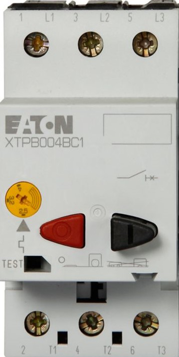
The Eaton XTPB010BC1 Motor Protector is a robust device designed to safeguard electric motors from potential damage caused by overload, short circuits, or phase failure. By providing reliable protection, it ensures the longevity and efficient operation of motors in industrial and commercial applications. This motor protector is particularly suited for use in motor control centers, automation systems, and standalone motor-driven equipment.
Explore Projects Built with Motor Protector
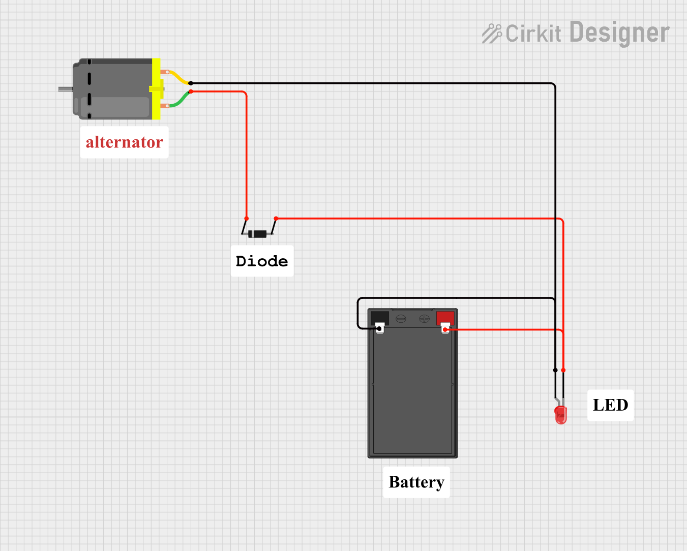
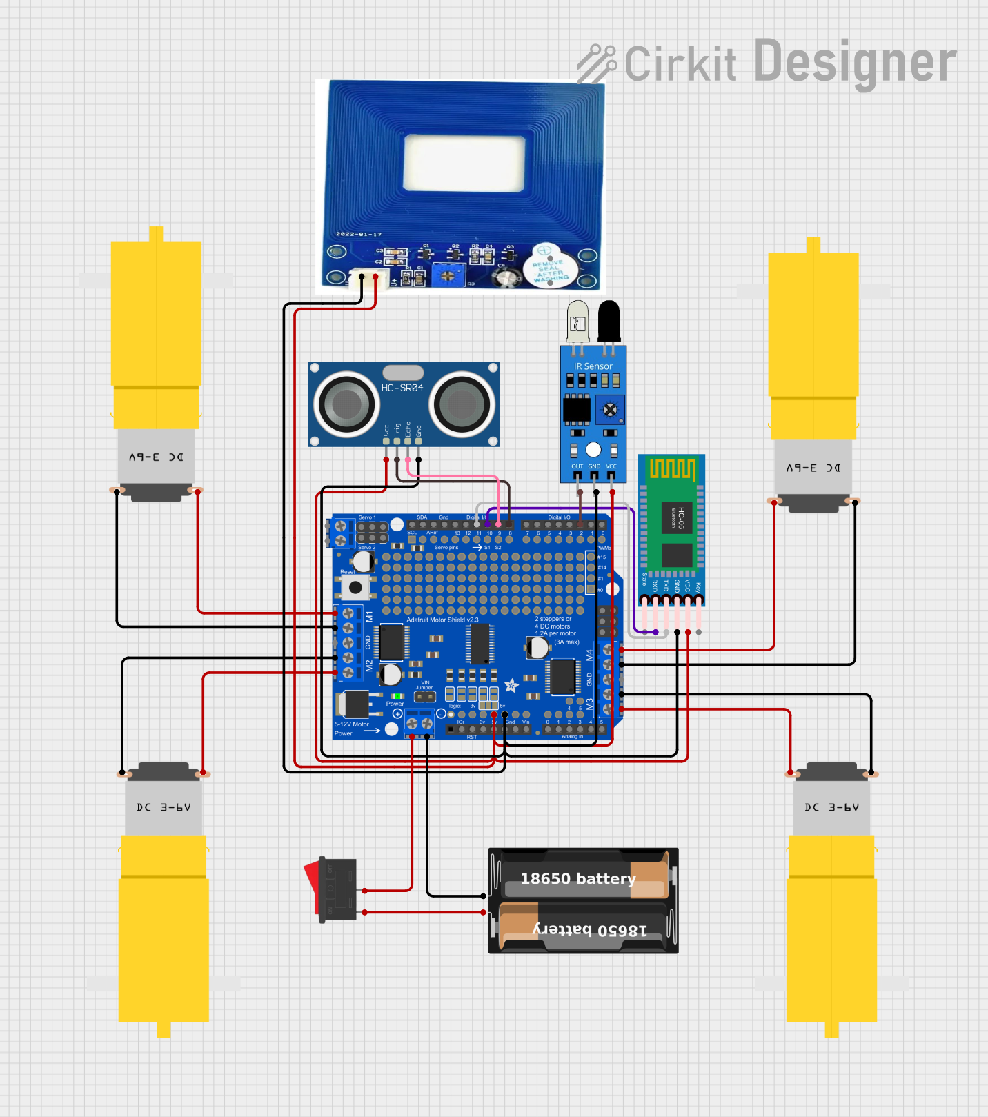
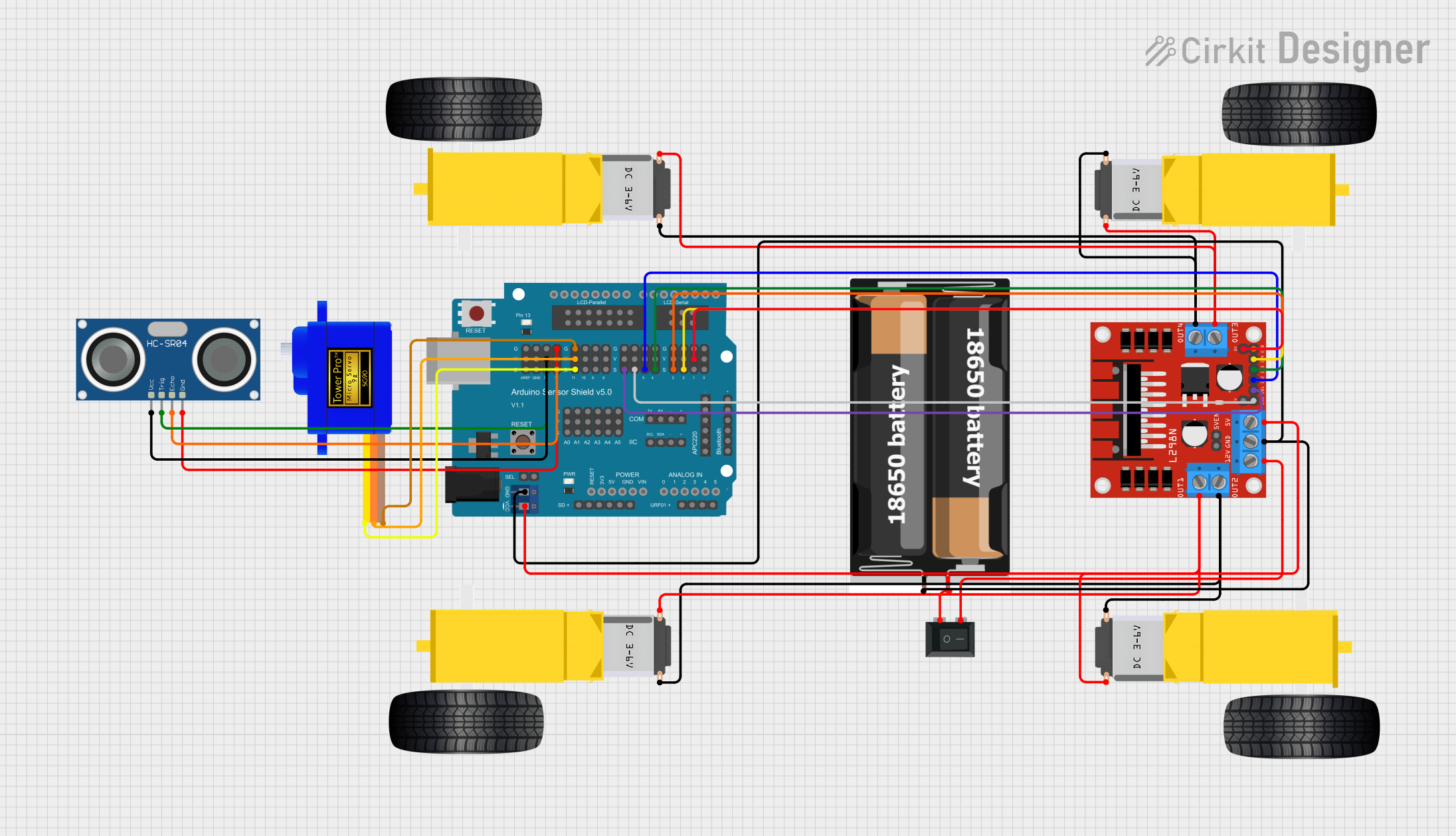
Explore Projects Built with Motor Protector
Common Applications and Use Cases
- Industrial machinery and conveyor systems
- HVAC systems and pumps
- Compressors and fans
- Automation systems requiring motor protection
- Electrical panels in manufacturing plants
Technical Specifications
The following table outlines the key technical details of the Eaton XTPB010BC1 Motor Protector:
| Parameter | Specification |
|---|---|
| Manufacturer | Eaton |
| Part Number | XTPB010BC1 |
| Rated Operational Voltage | Up to 690V AC |
| Rated Current Range | 6.3A to 10A |
| Short-Circuit Protection | Up to 100kA |
| Overload Protection | Adjustable thermal overload relay |
| Phase Failure Protection | Yes |
| Operating Temperature | -25°C to +55°C |
| Mounting Type | DIN rail or panel mount |
| Dimensions (H x W x D) | 90mm x 45mm x 76mm |
| Certifications | IEC/EN 60947-4-1, UL, CSA |
Pin Configuration and Descriptions
The Eaton XTPB010BC1 Motor Protector features screw terminals for electrical connections. The table below describes the terminal configuration:
| Terminal | Description |
|---|---|
| L1, L2, L3 | Input terminals for three-phase power supply |
| T1, T2, T3 | Output terminals to connect the motor |
| 95, 96 | Auxiliary contacts for overload trip signal (NC) |
| 97, 98 | Auxiliary contacts for overload trip signal (NO) |
| PE | Protective earth terminal |
Usage Instructions
How to Use the Component in a Circuit
- Mounting: Secure the motor protector on a DIN rail or panel using the provided mounting slots.
- Wiring:
- Connect the three-phase power supply to the input terminals (L1, L2, L3).
- Connect the motor leads to the output terminals (T1, T2, T3).
- Optionally, connect the auxiliary contacts (95, 96, 97, 98) to an external monitoring or control circuit.
- Ensure the protective earth (PE) terminal is properly grounded.
- Adjusting Overload Settings:
- Use the adjustment dial on the front of the device to set the rated motor current within the range of 6.3A to 10A.
- Refer to the motor's nameplate for the correct current rating.
- Testing:
- After installation, test the motor protector by simulating an overload condition to ensure proper tripping and protection.
Important Considerations and Best Practices
- Always verify the motor's rated current and set the overload protection accordingly.
- Ensure proper grounding to avoid electrical hazards.
- Regularly inspect the motor protector for signs of wear or damage.
- Avoid exceeding the rated voltage and current limits to prevent device failure.
- For applications involving an Arduino UNO or other microcontrollers, use the auxiliary contacts to monitor the motor protector's status.
Example Arduino Code for Monitoring
The following Arduino code demonstrates how to monitor the motor protector's auxiliary contacts for an overload trip signal:
// Define pins for auxiliary contacts
const int overloadNC = 2; // Normally Closed (NC) contact connected to pin 2
const int overloadNO = 3; // Normally Open (NO) contact connected to pin 3
const int ledPin = 13;    // LED to indicate overload condition

void setup() {
  pinMode(overloadNC, INPUT_PULLUP); // Configure NC contact as input with pull-up
  pinMode(overloadNO, INPUT_PULLUP); // Configure NO contact as input with pull-up
  pinMode(ledPin, OUTPUT);           // Configure LED pin as output
  Serial.begin(9600);                // Initialize serial communication
}

void loop() {
  // Read the state of the auxiliary contacts
  bool ncState = digitalRead(overloadNC);
  bool noState = digitalRead(overloadNO);

  // Check for overload condition
  if (ncState == HIGH && noState == LOW) {
    digitalWrite(ledPin, HIGH); // Turn on LED to indicate overload
    Serial.println("Overload detected! Motor protector has tripped.");
  } else {
    digitalWrite(ledPin, LOW);  // Turn off LED
    Serial.println("Motor is operating normally.");
  }

  delay(500); // Wait for 500ms before checking again
}
Troubleshooting and FAQs
Common Issues and Solutions
| Issue | Solution |
|---|---|
| Motor protector trips frequently | Verify the motor's current rating and adjust the overload setting accordingly. |
| No power to the motor | Check the input power supply and ensure proper wiring to the input terminals. |
| Auxiliary contacts not functioning | Inspect the wiring and ensure proper connection to the monitoring circuit. |
| Device overheating | Ensure adequate ventilation and avoid exceeding the rated current. |
| Motor protector does not trip during overload | Test the device using a simulated overload condition to verify functionality. |
FAQs
Can the XTPB010BC1 be used with single-phase motors?
Yes, but only two of the three input and output terminals (e.g., L1 and L2, T1 and T2) should be used. Ensure proper configuration for single-phase operation.What is the purpose of the auxiliary contacts?
The auxiliary contacts provide a signal to external circuits, such as alarms or controllers, when the motor protector trips due to an overload or fault.How often should the motor protector be tested?
It is recommended to test the motor protector at least once every six months to ensure reliable operation.Can this device be used in outdoor environments?
The XTPB010BC1 is not designed for outdoor use unless installed in a weatherproof enclosure.