Cirkit Designer Logo
Cirkit Designer
Your all-in-one circuit design IDE
Home / 
Component Documentation

How to Use Atmega168: Examples, Pinouts, and Specs

Image of Atmega168
Cirkit Designer LogoDesign with Atmega168 in Cirkit Designer

Introduction

The Atmega168 is a versatile and powerful microcontroller that belongs to Atmel's extensive AVR family. It is designed for a wide range of applications, from simple DIY projects to more complex embedded systems. With its RISC-based architecture, the Atmega168 provides a balanced combination of performance and power efficiency, making it an ideal choice for battery-operated devices, robotics, automation systems, and sensor interfacing.

Explore Projects Built with Atmega168
Use Cirkit Designer to design, explore, and prototype these projects online. Some projects support real-time simulation. Click "Open Project" to start designing instantly!
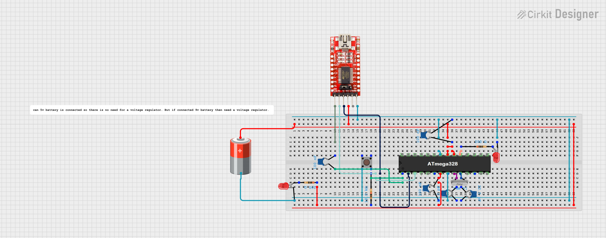
ATMEGA328 Battery-Powered LED Blinker with FTDI Programming
Image of Homemade Arduino using ATmega328: A project utilizing Atmega168 in a practical application
This circuit is a basic microcontroller setup using an ATMEGA328, powered by a 5V battery, and includes an FTDI programmer for serial communication. It features a pushbutton for reset functionality and two LEDs controlled by the microcontroller, with one LED blinking at a 1-second interval as programmed.
Cirkit Designer LogoOpen Project in Cirkit Designer
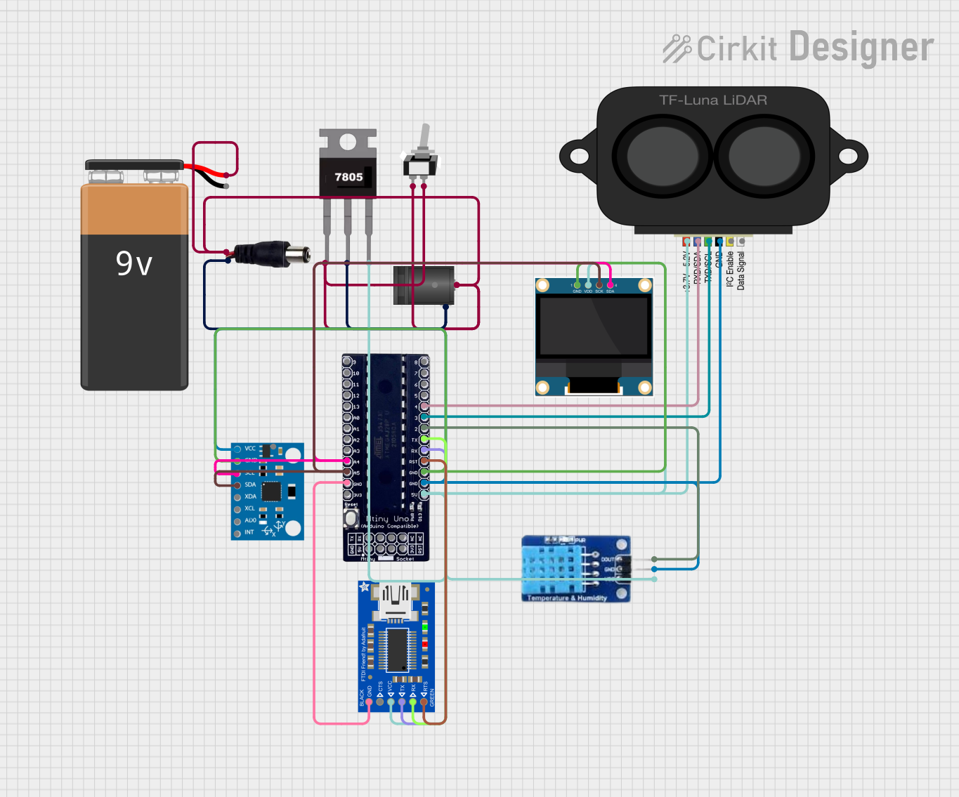
ATmega328P-Based Sensor Hub with OLED Display and LIDAR
Image of TILTPCB: A project utilizing Atmega168 in a practical application
This circuit features an Mtiny Uno ATmega328P microcontroller as its central processing unit, interfacing with a variety of sensors and peripherals. It includes a 0.96" OLED display and an MPU6050 accelerometer/gyroscope for user interface and motion sensing, respectively. The circuit also integrates a TF LUNA LIDAR for distance measurement, a DHT11 sensor for temperature and humidity readings, and uses a 9V battery with a 7805 voltage regulator for power management. Communication with a computer for programming and data exchange is facilitated by an Adafruit FTDI Friend module.
Cirkit Designer LogoOpen Project in Cirkit Designer
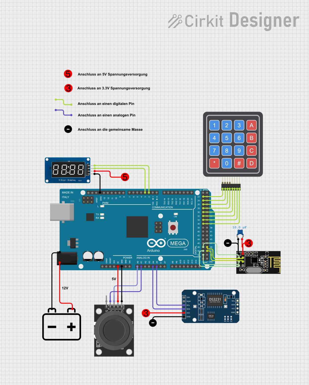
Arduino Mega 2560-Based Wireless Joystick-Controlled Display with RTC
Image of RH-WallE Sender Schaltplan (Cirkit Designer).png: A project utilizing Atmega168 in a practical application
This circuit is a multi-functional embedded system using an Arduino Mega 2560 as the central controller. It interfaces with various peripherals including a DS3231 RTC for timekeeping, an NRF24L01 for wireless communication, a KY-023 joystick for user input, a 4x4 keypad for additional input, and a TM1637 display for output. The system is powered by a combination of 3.3V and 5V sources.
Cirkit Designer LogoOpen Project in Cirkit Designer
Arduino Mega 2560 Based Security System with Fingerprint Authentication and SMS Alerts
Image of Door security system: A project utilizing Atmega168 in a practical application
This circuit features an Arduino Mega 2560 microcontroller interfaced with a SIM800L GSM module, two fingerprint scanners, an I2C LCD display, an IR sensor, and a piezo buzzer. Power management is handled by a PowerBoost 1000 Basic Pad USB, a TP4056 charging module, and a Li-ion 18650 battery, with an option to use a Mini AC-DC 110V-230V to 5V 700mA module for direct power supply. The primary functionality appears to be a security system with GSM communication capabilities, biometric access control, and visual/audible feedback.
Cirkit Designer LogoOpen Project in Cirkit Designer

Explore Projects Built with Atmega168

Use Cirkit Designer to design, explore, and prototype these projects online. Some projects support real-time simulation. Click "Open Project" to start designing instantly!
Image of Homemade Arduino using ATmega328: A project utilizing Atmega168 in a practical application
ATMEGA328 Battery-Powered LED Blinker with FTDI Programming
This circuit is a basic microcontroller setup using an ATMEGA328, powered by a 5V battery, and includes an FTDI programmer for serial communication. It features a pushbutton for reset functionality and two LEDs controlled by the microcontroller, with one LED blinking at a 1-second interval as programmed.
Cirkit Designer LogoOpen Project in Cirkit Designer
Image of TILTPCB: A project utilizing Atmega168 in a practical application
ATmega328P-Based Sensor Hub with OLED Display and LIDAR
This circuit features an Mtiny Uno ATmega328P microcontroller as its central processing unit, interfacing with a variety of sensors and peripherals. It includes a 0.96" OLED display and an MPU6050 accelerometer/gyroscope for user interface and motion sensing, respectively. The circuit also integrates a TF LUNA LIDAR for distance measurement, a DHT11 sensor for temperature and humidity readings, and uses a 9V battery with a 7805 voltage regulator for power management. Communication with a computer for programming and data exchange is facilitated by an Adafruit FTDI Friend module.
Cirkit Designer LogoOpen Project in Cirkit Designer
Image of RH-WallE Sender Schaltplan (Cirkit Designer).png: A project utilizing Atmega168 in a practical application
Arduino Mega 2560-Based Wireless Joystick-Controlled Display with RTC
This circuit is a multi-functional embedded system using an Arduino Mega 2560 as the central controller. It interfaces with various peripherals including a DS3231 RTC for timekeeping, an NRF24L01 for wireless communication, a KY-023 joystick for user input, a 4x4 keypad for additional input, and a TM1637 display for output. The system is powered by a combination of 3.3V and 5V sources.
Cirkit Designer LogoOpen Project in Cirkit Designer
Image of Door security system: A project utilizing Atmega168 in a practical application
Arduino Mega 2560 Based Security System with Fingerprint Authentication and SMS Alerts
This circuit features an Arduino Mega 2560 microcontroller interfaced with a SIM800L GSM module, two fingerprint scanners, an I2C LCD display, an IR sensor, and a piezo buzzer. Power management is handled by a PowerBoost 1000 Basic Pad USB, a TP4056 charging module, and a Li-ion 18650 battery, with an option to use a Mini AC-DC 110V-230V to 5V 700mA module for direct power supply. The primary functionality appears to be a security system with GSM communication capabilities, biometric access control, and visual/audible feedback.
Cirkit Designer LogoOpen Project in Cirkit Designer

Technical Specifications

Key Technical Details

  • Microcontroller: ATmega168
  • Operating Voltage: 1.8 - 5.5V
  • Input Voltage (recommended): 7-12V
  • Input Voltage (limits): 6-20V
  • Digital I/O Pins: 23
  • Analog Input Pins: 6
  • PWM Channels: 6
  • DC Current per I/O Pin: 40 mA
  • DC Current for 3.3V Pin: 50 mA
  • Flash Memory: 16 KB (of which 2 KB used by bootloader)
  • SRAM: 1 KB
  • EEPROM: 512 bytes
  • Clock Speed: 16 MHz

Pin Configuration and Descriptions

Pin Number Name Description
1 PC6 Reset Pin
2-3 PD0-PD1 Serial Communication (RX/TX)
4-5 PD2-PD3 External Interrupts (INT0/INT1)
6-11 PD4-PD7, PB0-PB1 General Purpose I/O
12-17 PB2-PB5, PC0-PC1 PWM Output/General I/O
18-23 PC2-PC5, ADC0-ADC5 Analog Input Pins
24-28 PC6-PC7, PD0-PD1, PD2 Additional I/O Pins
29 AREF Analog Reference Pin
30 GND Ground
31 AVCC Analog Power Supply
32 PB6 Oscillator Pin
33 PB7 Oscillator Pin

Usage Instructions

Integrating Atmega168 into a Circuit

  1. Power Supply: Ensure that the Atmega168 is powered with a stable voltage source between 1.8V and 5.5V. For most applications, a regulated 5V supply is recommended.

  2. Clock Source: Connect an external 16MHz crystal oscillator between pins PB6 and PB7 to provide a clock source for the microcontroller.

  3. Reset Circuit: Connect a 10kΩ pull-up resistor to the reset pin (PC6) and a push-button to ground to enable manual resetting of the microcontroller.

  4. Programming: Use an ISP (In-System Programmer) to upload firmware to the Atmega168. The SPI pins (MOSI, MISO, SCK, and RESET) are used for programming the device.

  5. I/O Configuration: Configure the digital and analog pins according to the requirements of your application. Remember to set the data direction registers appropriately.

Best Practices

  • Use decoupling capacitors (typically 100nF) near the power supply pins to filter out noise.
  • Avoid running I/O pins at their maximum current rating to ensure longevity.
  • Implement proper ESD (Electrostatic Discharge) precautions when handling the microcontroller.

Troubleshooting and FAQs

Common Issues

  • Microcontroller Not Responding: Ensure that the power supply is connected correctly and the clock source is functioning. Check the reset circuit for proper operation.
  • Incorrect Behavior: Verify that the firmware is correctly programmed and that the I/O pins are configured as intended. Check for shorts or open circuits in your design.

FAQs

  • Can I use the Atmega168 with Arduino IDE? Yes, the Atmega168 can be used with the Arduino IDE by selecting the appropriate board configuration.

  • What is the maximum voltage that can be applied to the I/O pins? The maximum voltage on any I/O pin should not exceed the operating voltage of the microcontroller, which is 5.5V.

  • How can I reduce power consumption? Utilize the power-down modes available in the Atmega168 and minimize the clock speed where possible.

Example Code for Arduino UNO

Below is an example of how to blink an LED connected to pin 13 on an Arduino UNO, which uses the Atmega168 microcontroller.

// Define the LED pin
const int ledPin = 13;

// the setup routine runs once when you press reset:
void setup() {
  // initialize the digital pin as an output.
  pinMode(ledPin, OUTPUT);
}

// the loop routine runs over and over again forever:
void loop() {
  digitalWrite(ledPin, HIGH);   // turn the LED on (HIGH is the voltage level)
  delay(1000);                  // wait for a second
  digitalWrite(ledPin, LOW);    // turn the LED off by making the voltage LOW
  delay(1000);                  // wait for a second
}

Remember to keep the code comments concise and within the 80-character line length limit. This example is simple enough to fit within those constraints.