Cirkit Designer Logo
Cirkit Designer
Your all-in-one circuit design IDE
Home / 
Component Documentation

How to Use PicAxe 18M2+: Examples, Pinouts, and Specs

Image of PicAxe 18M2+
Cirkit Designer LogoDesign with PicAxe 18M2+ in Cirkit Designer

Introduction

The PicAxe 18M2+ is a powerful and versatile microcontroller designed for hobbyists, educators, and professionals. It combines a BASIC programming environment with a wide range of input/output (I/O) capabilities, making it an excellent choice for controlling electronic projects and automating tasks. Its ease of use and flexibility make it ideal for applications such as robotics, data logging, home automation, and educational projects.

Common applications and use cases:

  • Robotics control systems
  • Sensor data acquisition and logging
  • Home automation and IoT projects
  • Educational tools for learning microcontroller programming
  • Prototyping and small-scale automation

Explore Projects Built with PicAxe 18M2+

Use Cirkit Designer to design, explore, and prototype these projects online. Some projects support real-time simulation. Click "Open Project" to start designing instantly!
Raspberry Pi Pico and OV7670 Camera-Based Robotic System with TFT Display
Image of REF Speed Bot V3 CKT: A project utilizing PicAxe 18M2+ in a practical application
This circuit features two Raspberry Pi Pico microcontrollers interfacing with various peripherals including an OV7670 camera module, a TFT display, and an OLED display. It also includes a multiplexer and a motor driver to control two planetary gearbox motors, powered by a battery and regulated through buck converters. The setup is designed for image capture, display, and motor control applications.
Cirkit Designer LogoOpen Project in Cirkit Designer
Raspberry Pi Pico-Based Navigation Assistant with Bluetooth and GPS
Image of sat_dish: compass example: A project utilizing PicAxe 18M2+ in a practical application
This circuit features a Raspberry Pi Pico microcontroller interfaced with an HC-05 Bluetooth module for wireless communication, an HMC5883L compass module for magnetic field measurement, and a GPS NEO 6M module for location tracking. The Pico is configured to communicate with the HC-05 via serial connection (TX/RX), with the compass module via I2C (SCL/SDA), and with the GPS module via serial (TX/RX). Common power (VCC) and ground (GND) lines are shared among all modules, indicating a unified power system.
Cirkit Designer LogoOpen Project in Cirkit Designer
Raspberry Pi-Controlled Drone with Brushless Motors and Camera Module
Image of ROV: A project utilizing PicAxe 18M2+ in a practical application
This circuit is designed for a multi-motor application, likely a drone or a similar vehicle, featuring eight brushless motors controlled by two 4-in-1 electronic speed controllers (ESCs). The ESCs are powered by a 3s2p 18650 battery pack and interfaced with a Pixhawk flight controller for motor management. Additionally, the system includes a Raspberry Pi 4B for advanced processing and control, which is connected to a NoIR camera module and a cooling fan, and a power module to supply and monitor the power to the Pixhawk.
Cirkit Designer LogoOpen Project in Cirkit Designer
Raspberry Pi Pico-Controlled Robot with Ultrasonic Navigation and Light Sensing
Image of Copy of MED412: A project utilizing PicAxe 18M2+ in a practical application
This circuit features a Raspberry Pi Pico microcontroller interfaced with various sensors and actuators. It controls a servo motor via PWM, reads an LDR sensor with a resistor in a voltage divider configuration, and interfaces with an HC-SR04 ultrasonic sensor. The circuit also includes a motor driver (L298N) to operate two DC gearmotors, with power regulation provided by a buck converter connected to a DC power source.
Cirkit Designer LogoOpen Project in Cirkit Designer

Explore Projects Built with PicAxe 18M2+

Use Cirkit Designer to design, explore, and prototype these projects online. Some projects support real-time simulation. Click "Open Project" to start designing instantly!
Image of REF Speed Bot V3 CKT: A project utilizing PicAxe 18M2+ in a practical application
Raspberry Pi Pico and OV7670 Camera-Based Robotic System with TFT Display
This circuit features two Raspberry Pi Pico microcontrollers interfacing with various peripherals including an OV7670 camera module, a TFT display, and an OLED display. It also includes a multiplexer and a motor driver to control two planetary gearbox motors, powered by a battery and regulated through buck converters. The setup is designed for image capture, display, and motor control applications.
Cirkit Designer LogoOpen Project in Cirkit Designer
Image of sat_dish: compass example: A project utilizing PicAxe 18M2+ in a practical application
Raspberry Pi Pico-Based Navigation Assistant with Bluetooth and GPS
This circuit features a Raspberry Pi Pico microcontroller interfaced with an HC-05 Bluetooth module for wireless communication, an HMC5883L compass module for magnetic field measurement, and a GPS NEO 6M module for location tracking. The Pico is configured to communicate with the HC-05 via serial connection (TX/RX), with the compass module via I2C (SCL/SDA), and with the GPS module via serial (TX/RX). Common power (VCC) and ground (GND) lines are shared among all modules, indicating a unified power system.
Cirkit Designer LogoOpen Project in Cirkit Designer
Image of ROV: A project utilizing PicAxe 18M2+ in a practical application
Raspberry Pi-Controlled Drone with Brushless Motors and Camera Module
This circuit is designed for a multi-motor application, likely a drone or a similar vehicle, featuring eight brushless motors controlled by two 4-in-1 electronic speed controllers (ESCs). The ESCs are powered by a 3s2p 18650 battery pack and interfaced with a Pixhawk flight controller for motor management. Additionally, the system includes a Raspberry Pi 4B for advanced processing and control, which is connected to a NoIR camera module and a cooling fan, and a power module to supply and monitor the power to the Pixhawk.
Cirkit Designer LogoOpen Project in Cirkit Designer
Image of Copy of MED412: A project utilizing PicAxe 18M2+ in a practical application
Raspberry Pi Pico-Controlled Robot with Ultrasonic Navigation and Light Sensing
This circuit features a Raspberry Pi Pico microcontroller interfaced with various sensors and actuators. It controls a servo motor via PWM, reads an LDR sensor with a resistor in a voltage divider configuration, and interfaces with an HC-SR04 ultrasonic sensor. The circuit also includes a motor driver (L298N) to operate two DC gearmotors, with power regulation provided by a buck converter connected to a DC power source.
Cirkit Designer LogoOpen Project in Cirkit Designer

Technical Specifications

The PicAxe 18M2+ microcontroller offers the following key technical features:

Specification Value
Operating Voltage 2.0V to 5.5V
Clock Speed 32 MHz (internal resonator)
Programming Language BASIC
I/O Pins 16 (including 6 analog inputs)
EEPROM 256 bytes
RAM 128 bytes
Program Memory 2048 lines of BASIC code
Communication Protocols Serial, I2C, SPI
Power Consumption Low power (nanoWatt technology)
Package Type 18-pin DIP

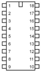
Pin Configuration and Descriptions

The PicAxe 18M2+ has an 18-pin layout, with each pin serving specific functions. Below is the pin configuration:

Pin Number Pin Name Description
1 V+ Positive power supply (2.0V to 5.5V)
2 C.5 Digital I/O or analog input (ADC channel 4)
3 C.4 Digital I/O or analog input (ADC channel 3)
4 C.3 Digital I/O or analog input (ADC channel 2)
5 C.2 Digital I/O or analog input (ADC channel 1)
6 C.1 Digital I/O or analog input (ADC channel 0)
7 C.0 Digital I/O
8 0V (GND) Ground
9 B.0 Digital I/O or PWM output
10 B.1 Digital I/O or PWM output
11 B.2 Digital I/O or serial input
12 B.3 Digital I/O or serial output
13 B.4 Digital I/O
14 B.5 Digital I/O
15 B.6 Digital I/O or I2C clock (SCL)
16 B.7 Digital I/O or I2C data (SDA)
17 RES Reset pin (active low)
18 V+ Positive power supply (2.0V to 5.5V)

Usage Instructions

How to Use the PicAxe 18M2+ in a Circuit

  1. Power Supply: Connect the V+ pin (pin 1 or 18) to a power source (2.0V to 5.5V) and the 0V (GND) pin (pin 8) to ground.
  2. Programming: Use the PicAxe Programming Editor software to write and upload BASIC code to the microcontroller via a serial programming cable.
  3. I/O Connections: Connect sensors, actuators, or other peripherals to the I/O pins. Use the appropriate pins for digital, analog, PWM, or communication functions.
  4. Communication: For serial communication, use pins B.2 (input) and B.3 (output). For I2C communication, use pins B.6 (SCL) and B.7 (SDA).

Important Considerations and Best Practices

  • Decoupling Capacitor: Place a 0.1 µF capacitor between V+ and GND to stabilize the power supply.
  • Pull-Up Resistors: Use pull-up resistors on the I2C lines (B.6 and B.7) for proper communication.
  • Programming Cable: Ensure the serial programming cable is correctly connected to avoid upload errors.
  • Pin Protection: Avoid exceeding the voltage and current limits of the I/O pins to prevent damage.

Example Code for Arduino UNO Integration

The PicAxe 18M2+ can communicate with an Arduino UNO via serial communication. Below is an example of Arduino code to send data to the PicAxe:

// Arduino code to send data to PicAxe 18M2+ via serial communication
void setup() {
  Serial.begin(4800); // Initialize serial communication at 4800 baud
}

void loop() {
  Serial.println("Hello PicAxe!"); // Send a message to the PicAxe
  delay(1000); // Wait for 1 second before sending the next message
}

On the PicAxe side, you can use the following BASIC code to receive and display the message:

' PicAxe BASIC code to receive data from Arduino
main:
  serin B.2, N4800, b0  ' Receive data on pin B.2 at 4800 baud
  sertxd ("Received: ", b0, 13, 10) ' Send received data to the PC via serial
  goto main             ' Repeat the process

Troubleshooting and FAQs

Common Issues and Solutions

  1. Problem: The PicAxe does not respond to programming commands.

    • Solution: Check the serial programming cable connections and ensure the correct COM port is selected in the PicAxe Programming Editor.
  2. Problem: The microcontroller resets unexpectedly.

    • Solution: Verify the power supply voltage is within the specified range (2.0V to 5.5V). Add a decoupling capacitor if necessary.
  3. Problem: I2C communication is not working.

    • Solution: Ensure pull-up resistors (typically 4.7 kΩ) are connected to the SCL and SDA lines. Check the wiring and device addresses.
  4. Problem: Analog readings are inaccurate.

    • Solution: Ensure the analog input voltage does not exceed the supply voltage. Use proper grounding and shielding to reduce noise.

FAQs

  • Q: Can the PicAxe 18M2+ run on batteries?

    • A: Yes, it can operate on batteries as long as the voltage is between 2.0V and 5.5V.
  • Q: What is the maximum current output of the I/O pins?

    • A: Each I/O pin can source or sink up to 20 mA, with a total maximum current of 90 mA for all pins combined.
  • Q: Can I use the PicAxe 18M2+ with a breadboard?

    • A: Yes, the 18-pin DIP package is breadboard-friendly, making it easy to prototype circuits.
  • Q: Is the PicAxe 18M2+ compatible with other microcontrollers?

    • A: Yes, it can communicate with other microcontrollers (e.g., Arduino) via serial, I2C, or SPI protocols.