How to Use Time Delay Relay: Examples, Pinouts, and Specs
Introduction
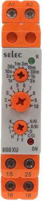
The Time Delay Relay (Selec 600XU-A-1-CU) is an electronic component designed to open or close a circuit after a predetermined time delay. This versatile relay is widely used in automation, industrial control systems, and timing applications. It provides precise control over timing functions, making it ideal for applications such as motor control, lighting systems, and sequential operations.
Explore Projects Built with Time Delay Relay


Explore Projects Built with Time Delay Relay
Common Applications and Use Cases
- Industrial automation systems
- HVAC systems for delayed fan or compressor control
- Sequential control in manufacturing processes
- Lighting systems with delayed activation or deactivation
- Motor start/stop delay circuits
- Safety systems requiring timed responses
Technical Specifications
The following table outlines the key technical details of the Selec 600XU-A-1-CU Time Delay Relay:
| Parameter | Specification |
|---|---|
| Manufacturer | Selec |
| Part ID | 600XU-A-1-CU |
| Operating Voltage | 12V DC / 24V DC / 110V AC / 230V AC |
| Time Delay Range | 0.1 seconds to 9999 hours |
| Contact Configuration | SPDT (Single Pole Double Throw) |
| Contact Rating | 5A at 230V AC / 30V DC |
| Power Consumption | < 3W |
| Mounting Type | DIN Rail |
| Operating Temperature | -10°C to +55°C |
| Dimensions | 48mm x 48mm x 90mm |
| Weight | Approximately 150g |
Pin Configuration and Descriptions
The Selec 600XU-A-1-CU Time Delay Relay has the following pin configuration:
| Pin Number | Label | Description |
|---|---|---|
| 1 | A1 | Positive supply voltage |
| 2 | A2 | Negative supply voltage |
| 3 | 15 | Common terminal for relay contacts |
| 4 | 16 | Normally Closed (NC) contact |
| 5 | 18 | Normally Open (NO) contact |
Usage Instructions
How to Use the Component in a Circuit
- Power Supply Connection: Connect the appropriate supply voltage to pins A1 (positive) and A2 (negative). Ensure the voltage matches the relay's operating voltage range.
- Load Connection:
- Connect the load to the relay's output terminals (15, 16, and 18).
- Use the Normally Open (NO) contact (15 to 18) if you want the circuit to close after the delay.
- Use the Normally Closed (NC) contact (15 to 16) if you want the circuit to open after the delay.
- Set the Time Delay: Use the front-panel rotary switches or digital interface (depending on the model) to set the desired time delay.
- Trigger the Relay: Apply the input signal or power to activate the relay. The relay will operate after the set time delay.
Important Considerations and Best Practices
- Voltage Compatibility: Ensure the supply voltage matches the relay's rated voltage to avoid damage.
- Load Rating: Do not exceed the relay's contact rating (5A at 230V AC or 30V DC).
- Mounting: Securely mount the relay on a DIN rail to prevent vibration or movement.
- Environmental Conditions: Operate the relay within the specified temperature range (-10°C to +55°C).
- Debouncing: If using the relay with a microcontroller, implement debouncing to avoid false triggering.
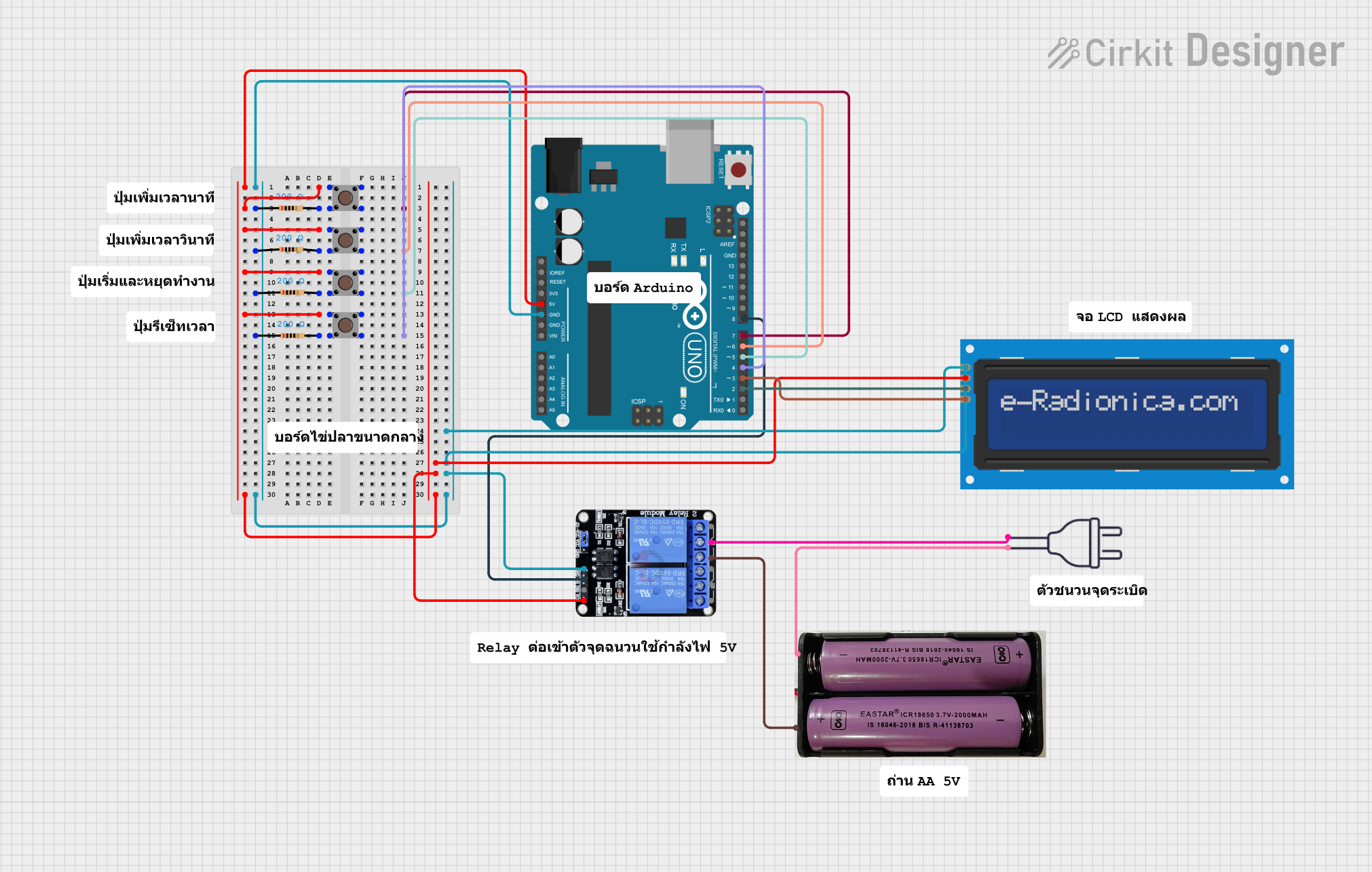
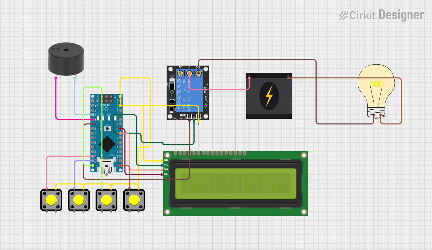
Example: Using the Relay with an Arduino UNO
Below is an example of how to use the Selec 600XU-A-1-CU Time Delay Relay with an Arduino UNO to control a light with a 5-second delay.
// Example: Controlling a Time Delay Relay with Arduino UNO
// This code activates the relay for 5 seconds after a button press.

const int relayPin = 7;  // Pin connected to the relay module
const int buttonPin = 2; // Pin connected to the button
int buttonState = 0;     // Variable to store button state

void setup() {
  pinMode(relayPin, OUTPUT);  // Set relay pin as output
  pinMode(buttonPin, INPUT);  // Set button pin as input
  digitalWrite(relayPin, LOW); // Ensure relay is off at startup
}

void loop() {
  buttonState = digitalRead(buttonPin); // Read the button state

  if (buttonState == HIGH) { // If button is pressed
    digitalWrite(relayPin, HIGH); // Activate the relay
    delay(5000); // Wait for 5 seconds
    digitalWrite(relayPin, LOW); // Deactivate the relay
  }
}
Troubleshooting and FAQs
Common Issues and Solutions
Relay Does Not Activate:
- Cause: Incorrect supply voltage or loose connections.
- Solution: Verify the supply voltage and ensure all connections are secure.
Relay Activates but Load Does Not Operate:
- Cause: Load exceeds the relay's contact rating or incorrect wiring.
- Solution: Check the load specifications and wiring connections.
Unstable Operation:
- Cause: Electrical noise or insufficient power supply.
- Solution: Use a decoupling capacitor across the power supply and ensure a stable power source.
Time Delay Not Accurate:
- Cause: Incorrect time delay settings.
- Solution: Recheck and adjust the time delay settings.
FAQs
Q1: Can this relay be used with DC loads?
A1: Yes, the Selec 600XU-A-1-CU can handle DC loads up to 30V DC at 5A.
Q2: How do I reset the relay after activation?
A2: The relay automatically resets after the time delay. For manual reset, disconnect and reconnect the power supply.
Q3: Can I use this relay for high-power applications?
A3: No, this relay is rated for a maximum of 5A. For higher power, use an additional contactor.
Q4: Is the relay programmable?
A4: Yes, the time delay can be programmed using the front-panel controls or digital interface.
This concludes the documentation for the Selec 600XU-A-1-CU Time Delay Relay.