How to Use Intel Edison Arduinobreakout: Examples, Pinouts, and Specs
Introduction
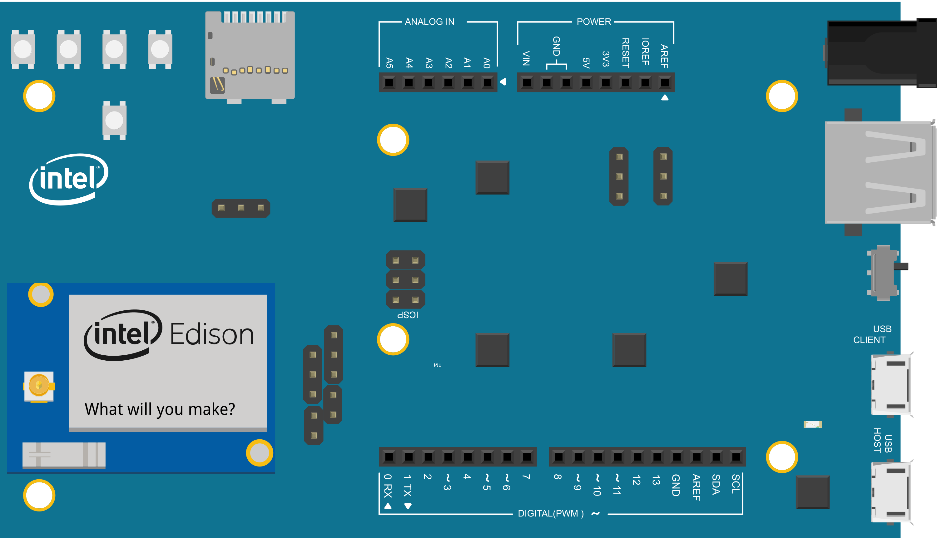
The Intel Edison Arduino Breakout is a versatile and powerful breakout board designed to simplify the prototyping and development process with the Intel Edison module. This board extends the capabilities of the Edison module by providing easy access to a range of interfaces such as General Purpose Input/Output (GPIO), Inter-Integrated Circuit (I2C), and Universal Asynchronous Receiver-Transmitter (UART). It is ideal for developers looking to create Internet of Things (IoT) devices, wearable technology, and other innovative projects.
Explore Projects Built with Intel Edison Arduinobreakout

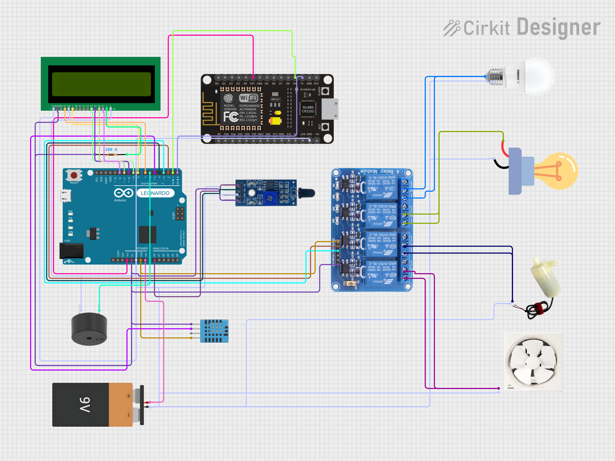
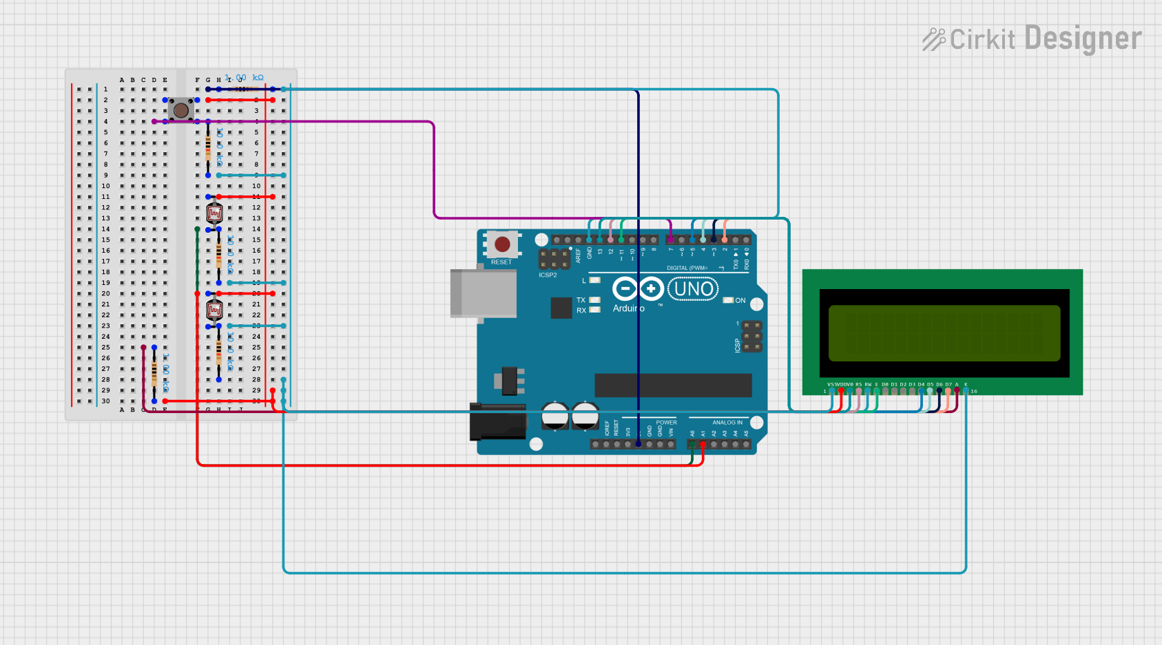
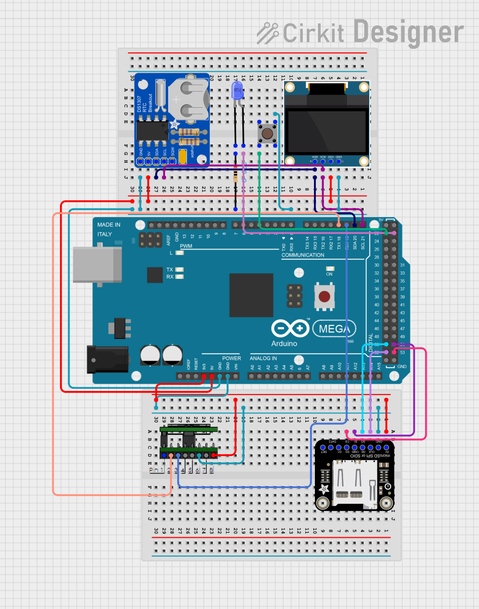
Explore Projects Built with Intel Edison Arduinobreakout
Common Applications and Use Cases
- IoT devices
- Wearable technology
- Rapid prototyping
- Educational projects
- Robotics
- Home automation systems
Technical Specifications
Key Technical Details
- Voltage Input (Vin): 7-15V
- GPIO Voltage Levels: 1.8V
- I2C Interface: 1.8V level, up to 3.4 Mbps
- UART Interface: 1.8V level, up to 115200 bps
- Power Ratings: 500mA max for the Edison module
Pin Configuration and Descriptions
| Pin Number | Description | Type | Voltage Level | Notes |
|---|---|---|---|---|
| 1 | GPIO 0 | Digital | 1.8V | Configurable as input or output |
| 2 | GPIO 1 | Digital | 1.8V | Configurable as input or output |
| 3 | I2C SDA | I2C | 1.8V | Data line for I2C interface |
| 4 | I2C SCL | I2C | 1.8V | Clock line for I2C interface |
| 5 | UART RX | UART | 1.8V | Receive line for UART |
| 6 | UART TX | UART | 1.8V | Transmit line for UART |
| ... | ... | ... | ... | ... |
| N | Vin | Power | 7-15V | Voltage input for the board |
Note: This table is not exhaustive and only includes a selection of the available pins.
Usage Instructions
How to Use the Component in a Circuit
Powering the Board:
- Connect a 7-15V DC power supply to the Vin pin and ground.
- Ensure that the power supply is capable of providing sufficient current for your application.
Connecting to GPIO:
- Use the GPIO pins to interface with sensors, actuators, or other digital devices.
- Remember that the GPIO operates at 1.8V logic levels.
Using I2C Interface:
- Connect I2C-compatible devices to the SDA and SCL pins.
- Ensure that the devices are compatible with 1.8V logic levels or use level shifters if necessary.
Utilizing UART Interface:
- Connect UART devices to the RX and TX pins for serial communication.
- Configure the baud rate to match the connected devices.
Important Considerations and Best Practices
- Voltage Levels: Be mindful of the 1.8V logic levels to prevent damage to the Edison module and connected devices.
- Current Limitations: Do not exceed the maximum current rating of 500mA for the Edison module.
- Static Discharge: Handle the board with care to avoid static discharge that can damage the electronics.
- Firmware Updates: Keep the Edison module firmware up to date for optimal performance and compatibility.
Troubleshooting and FAQs
Common Issues
- Power Issues: If the board does not power on, check the power supply and connections.
- I2C Communication Failure: Ensure that the I2C devices are correctly addressed and that there are no conflicts on the bus.
- UART Communication Errors: Verify the baud rate and ensure that the TX and RX lines are not reversed.
Solutions and Tips for Troubleshooting
- Check Connections: Double-check all wiring and connections for correctness and secure fit.
- Use a Logic Analyzer: A logic analyzer can help diagnose communication issues on I2C and UART interfaces.
- Consult the Community: The Intel Edison community is a valuable resource for troubleshooting and support.
FAQs
Q: Can I use 5V logic devices with the Edison Arduino Breakout? A: No, the board operates at 1.8V logic levels. Use level shifters for interfacing with 5V devices.
Q: How do I update the firmware on my Edison module? A: Firmware updates can be performed using the Intel Edison Configuration Tool available on the Intel website.
Q: Is the Edison Arduino Breakout compatible with standard Arduino shields? A: Yes, it is designed to be physically and electrically compatible with many Arduino shields.
For further assistance, please refer to the Intel Edison community forums or the official Intel support channels.
Note: This documentation is a general guide and may not cover all aspects of the Intel Edison Arduino Breakout. Always refer to the official Intel Edison documentation for complete and accurate information.