How to Use esp32 type c: Examples, Pinouts, and Specs
Introduction
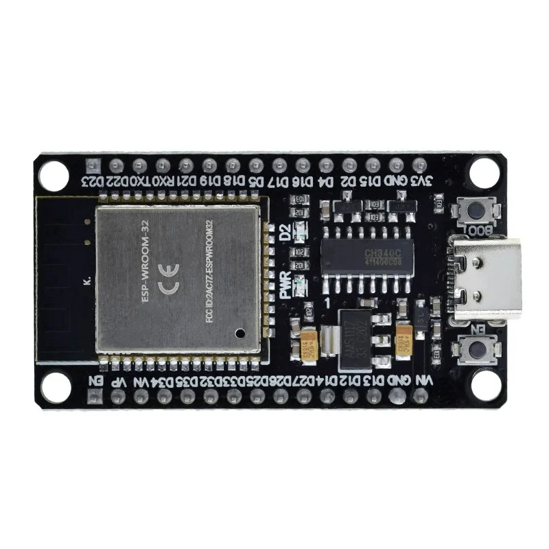
The ESP32 Type-C is a versatile microcontroller module that integrates Wi-Fi and Bluetooth capabilities, making it ideal for IoT (Internet of Things) applications. It features a USB Type-C interface for power and programming, offering a modern and convenient connection standard. The ESP32 Type-C is widely used in smart home devices, wearable electronics, industrial automation, and wireless sensor networks due to its powerful dual-core processor and extensive connectivity options.
Explore Projects Built with esp32 type c
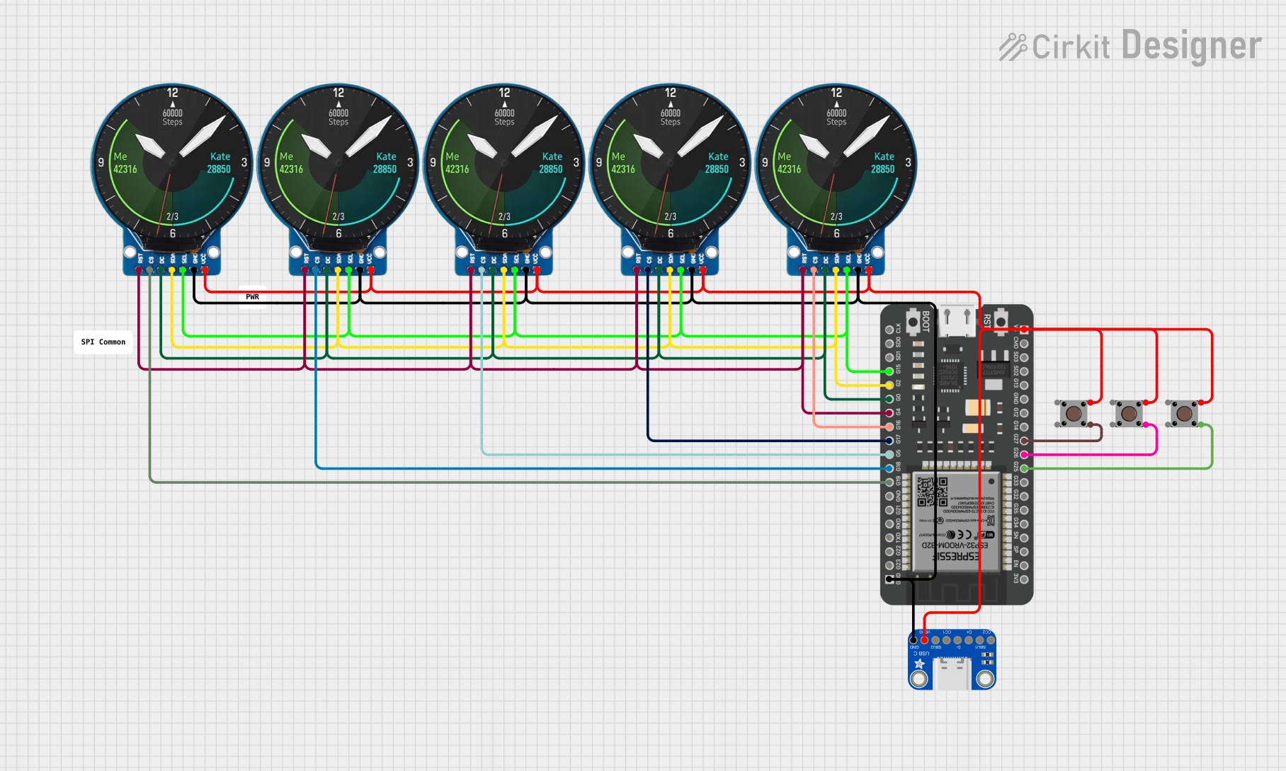
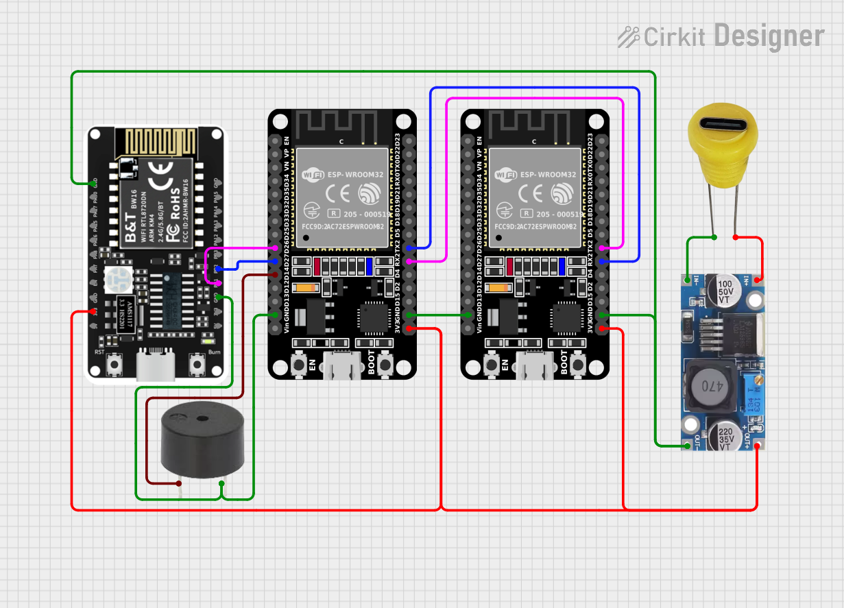


Explore Projects Built with esp32 type c
Technical Specifications
- Microcontroller: ESP32-D0WDQ6 (dual-core Xtensa LX6 processor)
- Clock Speed: Up to 240 MHz
- Flash Memory: 4 MB (varies by model)
- SRAM: 520 KB
- Wi-Fi: 802.11 b/g/n (2.4 GHz)
- Bluetooth: v4.2 BR/EDR and BLE
- Operating Voltage: 3.3V
- Input Voltage (via USB Type-C): 5V
- GPIO Pins: 34 (multipurpose)
- ADC Channels: 18 (12-bit resolution)
- DAC Channels: 2
- PWM Outputs: 16
- Communication Protocols: UART, SPI, I2C, I2S, CAN, Ethernet
- Power Consumption: Ultra-low power modes available
- Dimensions: Varies by board design
Pin Configuration and Descriptions
| Pin Name | Type | Description |
|---|---|---|
| VIN | Power Input | Input voltage (5V) when powered via USB Type-C. |
| 3V3 | Power Output | Regulated 3.3V output from the onboard voltage regulator. |
| GND | Ground | Ground connection. |
| EN | Input | Enable pin. Pulling this pin low resets the module. |
| GPIO0 | I/O | General-purpose I/O pin. Used for boot mode selection during programming. |
| GPIO1-34 | I/O | General-purpose I/O pins with multiple functions (PWM, ADC, UART, etc.). |
| TXD0 | Output | UART0 transmit pin. |
| RXD0 | Input | UART0 receive pin. |
| DAC1, DAC2 | Output | Digital-to-Analog Converter outputs. |
| ADC1_0-ADC1_7 | Input | Analog-to-Digital Converter inputs (12-bit resolution). |
| SCL, SDA | I/O | I2C clock and data lines. |
| MOSI, MISO, SCK | I/O | SPI communication pins. |
Usage Instructions
How to Use the ESP32 Type-C in a Circuit
- Powering the Module: Connect the ESP32 Type-C to a 5V power source via the USB Type-C port. Alternatively, you can power it through the VIN pin with a regulated 5V supply.
- Programming: Use the USB Type-C connection to upload code to the ESP32 using the Arduino IDE or other compatible development environments.
- Connecting Peripherals: Use the GPIO pins to interface with sensors, actuators, and other peripherals. Ensure that the voltage levels are compatible (3.3V logic).
- Wi-Fi and Bluetooth Setup: Configure the Wi-Fi and Bluetooth settings in your code to enable wireless communication.
Important Considerations and Best Practices
- Always use a level shifter when interfacing 5V devices with the ESP32's 3.3V GPIO pins to prevent damage.
- Avoid drawing excessive current from the 3V3 pin, as it is limited by the onboard voltage regulator.
- Use decoupling capacitors near the power pins to reduce noise and improve stability.
- When using ADC pins, ensure the input voltage does not exceed 3.3V to avoid damaging the module.
Example Code for Arduino UNO Integration
Below is an example of using the ESP32 Type-C to connect to a Wi-Fi network and control an LED:
#include <WiFi.h> // Include the Wi-Fi library

// Replace with your network credentials
const char* ssid = "Your_SSID";
const char* password = "Your_PASSWORD";

const int ledPin = 2; // GPIO2 is connected to the onboard LED

void setup() {
  pinMode(ledPin, OUTPUT); // Set the LED pin as an output
  Serial.begin(115200);    // Initialize serial communication

  // Connect to Wi-Fi
  Serial.print("Connecting to Wi-Fi");
  WiFi.begin(ssid, password);
  while (WiFi.status() != WL_CONNECTED) {
    delay(500);
    Serial.print(".");
  }
  Serial.println("\nWi-Fi connected!");
  Serial.print("IP Address: ");
  Serial.println(WiFi.localIP());
}

void loop() {
  digitalWrite(ledPin, HIGH); // Turn the LED on
  delay(1000);                // Wait for 1 second
  digitalWrite(ledPin, LOW);  // Turn the LED off
  delay(1000);                // Wait for 1 second
}
Troubleshooting and FAQs
Common Issues and Solutions
ESP32 Not Detected by Computer:
- Ensure the USB Type-C cable supports data transfer (not just charging).
- Check if the correct COM port is selected in the Arduino IDE.
- Install the necessary USB drivers for the ESP32.
Wi-Fi Connection Fails:
- Double-check the SSID and password in your code.
- Ensure the Wi-Fi network is within range and not overloaded.
GPIO Pins Not Responding:
- Verify that the pins are not being used for other functions (e.g., boot mode).
- Check for short circuits or incorrect wiring.
Module Overheating:
- Ensure the input voltage does not exceed 5V.
- Avoid drawing excessive current from the GPIO pins.
FAQs
Q: Can I power the ESP32 Type-C with a battery?
A: Yes, you can use a 3.7V LiPo battery connected to the 3V3 pin or a 5V source connected to the VIN pin.Q: How do I reset the ESP32?
A: Press the onboard reset button or pull the EN pin low momentarily.Q: Can the ESP32 Type-C handle 5V logic on GPIO pins?
A: No, the GPIO pins are 3.3V logic. Use a level shifter for 5V devices.Q: Is the ESP32 Type-C compatible with Arduino libraries?
A: Yes, the ESP32 is supported by the Arduino IDE and many libraries are available for it.