How to Use ESP32 (30 pin): Examples, Pinouts, and Specs
Introduction
The ESP32 is a powerful microcontroller with integrated Wi-Fi and Bluetooth capabilities, designed for IoT applications and embedded systems. With its 30-pin configuration, the ESP32 offers a wide range of GPIO (General Purpose Input/Output) pins, ADC (Analog-to-Digital Converter) channels, PWM (Pulse Width Modulation) outputs, and communication protocols such as UART, SPI, and I2C. Its dual-core processor and low-power modes make it suitable for both high-performance and energy-efficient applications.
Explore Projects Built with ESP32 (30 pin)


Explore Projects Built with ESP32 (30 pin)
Common Applications and Use Cases
- IoT devices and smart home automation
- Wireless sensor networks
- Wearable technology
- Robotics and drones
- Industrial automation
- Real-time data monitoring and logging
Technical Specifications
Key Technical Details
| Specification | Value |
|---|---|
| Microcontroller | Tensilica Xtensa LX6 Dual-Core Processor |
| Clock Speed | Up to 240 MHz |
| Flash Memory | 4 MB (varies by model) |
| SRAM | 520 KB |
| Wi-Fi Standard | 802.11 b/g/n |
| Bluetooth Version | Bluetooth 4.2 + BLE |
| Operating Voltage | 3.3V |
| Input Voltage Range | 5V (via USB) or 3.3V (via VIN pin) |
| GPIO Pins | 30 |
| ADC Channels | 18 (12-bit resolution) |
| PWM Outputs | Up to 16 |
| Communication Protocols | UART, SPI, I2C, CAN, I2S |
| Power Consumption | Ultra-low power modes available |
| Operating Temperature Range | -40°C to 125°C |
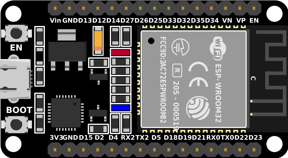
Pin Configuration and Descriptions
The ESP32 (30-pin variant) has the following pinout:
| Pin Number | Pin Name | Function Description |
|---|---|---|
| 1 | EN | Enable pin (active high) |
| 2 | IO1 (TX0) | UART0 Transmit (TX) |
| 3 | IO3 (RX0) | UART0 Receive (RX) |
| 4 | IO4 | GPIO4, ADC2_CH0, Touch4 |
| 5 | IO5 | GPIO5, ADC2_CH1, Touch5 |
| 6 | IO6 | GPIO6, SPI_CLK (default for flash) |
| 7 | IO7 | GPIO7, SPI_DATA0 (default for flash) |
| 8 | IO8 | GPIO8, SPI_DATA1 (default for flash) |
| 9 | IO9 | GPIO9, SPI_DATA2 (default for flash) |
| 10 | IO10 | GPIO10, SPI_DATA3 (default for flash) |
| 11 | IO11 | GPIO11, SPI_CLK (default for flash) |
| 12 | IO12 | GPIO12, ADC2_CH5, Touch2 |
| 13 | IO13 | GPIO13, ADC2_CH4, Touch3 |
| 14 | IO14 | GPIO14, ADC2_CH6, Touch6 |
| 15 | IO15 | GPIO15, ADC2_CH3, Touch7 |
| 16 | IO16 | GPIO16, ADC2_CH2, Touch8 |
| 17 | IO17 | GPIO17, ADC2_CH1, Touch9 |
| 18 | IO18 | GPIO18, SPI_CLK, PWM |
| 19 | IO19 | GPIO19, SPI_MISO, PWM |
| 20 | IO21 | GPIO21, I2C SDA, PWM |
| 21 | IO22 | GPIO22, I2C SCL, PWM |
| 22 | IO23 | GPIO23, SPI_MOSI, PWM |
| 23 | GND | Ground |
| 24 | 3V3 | 3.3V Power Output |
| 25 | VIN | Input Voltage (5V or 3.3V) |
| 26 | IO25 | GPIO25, ADC2_CH8, DAC1 |
| 27 | IO26 | GPIO26, ADC2_CH9, DAC2 |
| 28 | IO27 | GPIO27, ADC2_CH7 |
| 29 | IO32 | GPIO32, ADC1_CH4, Touch9 |
| 30 | IO33 | GPIO33, ADC1_CH5, Touch8 |
Usage Instructions
How to Use the ESP32 in a Circuit
Powering the ESP32:
- Use a USB cable to supply 5V via the micro-USB port.
- Alternatively, provide 3.3V directly to the VIN pin. Ensure the power source is stable.
Connecting GPIO Pins:
- Use GPIO pins for digital input/output, PWM, or ADC.
- Avoid using GPIO6–GPIO11 for general purposes as they are connected to the internal flash.
Programming the ESP32:
- Install the ESP32 board package in the Arduino IDE or use the ESP-IDF framework.
- Connect the ESP32 to your computer via USB and select the correct COM port.
Uploading Code:
- Write your code in the Arduino IDE or ESP-IDF.
- Press the "Upload" button in the IDE to flash the code to the ESP32.
Important Considerations and Best Practices
- Voltage Levels: Ensure all connected peripherals operate at 3.3V logic levels to avoid damaging the ESP32.
- Boot Mode: If the ESP32 fails to boot, check the EN and IO0 pins. IO0 must be LOW during programming.
- Wi-Fi and Bluetooth: Avoid using ADC2 channels when Wi-Fi is active, as they share resources.
Example Code for Arduino UNO Integration
Below is an example of using the ESP32 to blink an LED connected to GPIO2:
// Define the GPIO pin for the LED
#define LED_PIN 2

void setup() {
  pinMode(LED_PIN, OUTPUT); // Set GPIO2 as an output pin
}

void loop() {
  digitalWrite(LED_PIN, HIGH); // Turn the LED on
  delay(1000);                 // Wait for 1 second
  digitalWrite(LED_PIN, LOW);  // Turn the LED off
  delay(1000);                 // Wait for 1 second
}
Troubleshooting and FAQs
Common Issues and Solutions
ESP32 Not Detected by Computer:
- Ensure the USB cable is functional and supports data transfer.
- Install the correct USB-to-serial driver (e.g., CP2102 or CH340).
Code Upload Fails:
- Check that the correct COM port is selected in the IDE.
- Hold the BOOT button while uploading to force the ESP32 into programming mode.
Wi-Fi Connection Issues:
- Verify the SSID and password in your code.
- Ensure the router operates on a 2.4 GHz band, as the ESP32 does not support 5 GHz.
Random Resets or Instability:
- Use a stable power supply with sufficient current (at least 500 mA).
- Add capacitors (e.g., 10 µF and 0.1 µF) near the VIN and GND pins to reduce noise.
FAQs
Q: Can I use the ESP32 with 5V peripherals?
A: No, the ESP32 operates at 3.3V logic levels. Use a level shifter for 5V peripherals.
Q: How do I use the ESP32's Bluetooth?
A: Use the BluetoothSerial library in the Arduino IDE or the ESP-IDF Bluetooth stack.
Q: Can I power the ESP32 with batteries?
A: Yes, you can use a LiPo battery with a 3.7V output or a 5V power bank connected to the USB port.
Q: What is the maximum current draw of the ESP32?
A: The ESP32 can draw up to 250 mA during peak operation, especially when Wi-Fi is active.