
How to Use Generic Brushed DC Motor: Examples, Pinouts, and Specs
 Design with Generic Brushed DC Motor in Cirkit Designer
Introduction
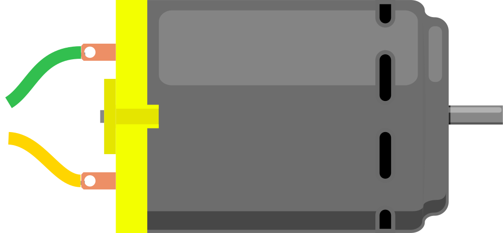
A Generic Brushed DC Motor is a type of electric motor that converts direct current (DC) electrical energy into mechanical energy. It uses brushes and a commutator to deliver current to the motor windings, enabling the motor to rotate. These motors are widely used due to their simplicity, reliability, and cost-effectiveness.
Explore Projects Built with Generic Brushed DC Motor
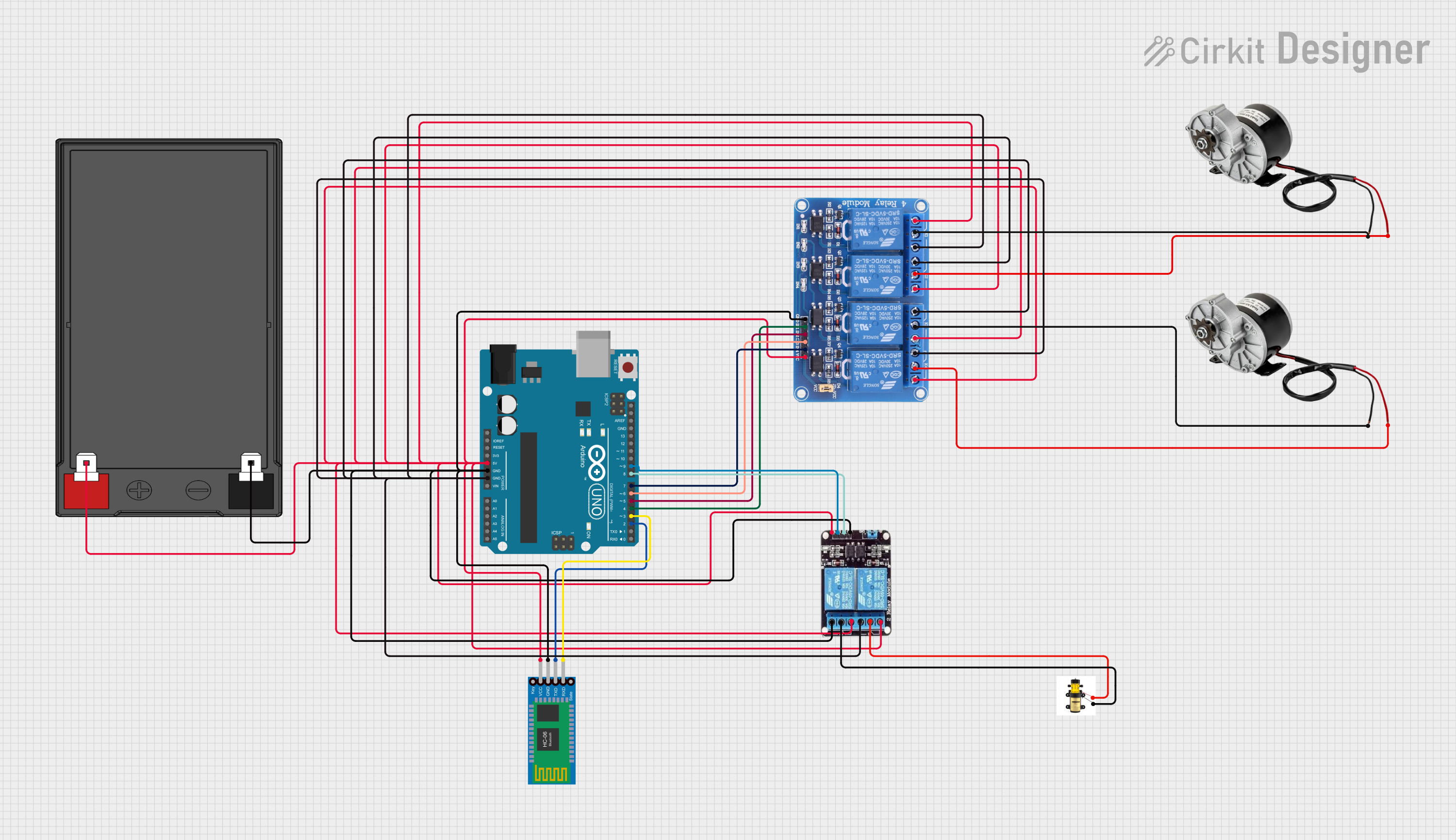 Open Project in Cirkit Designer
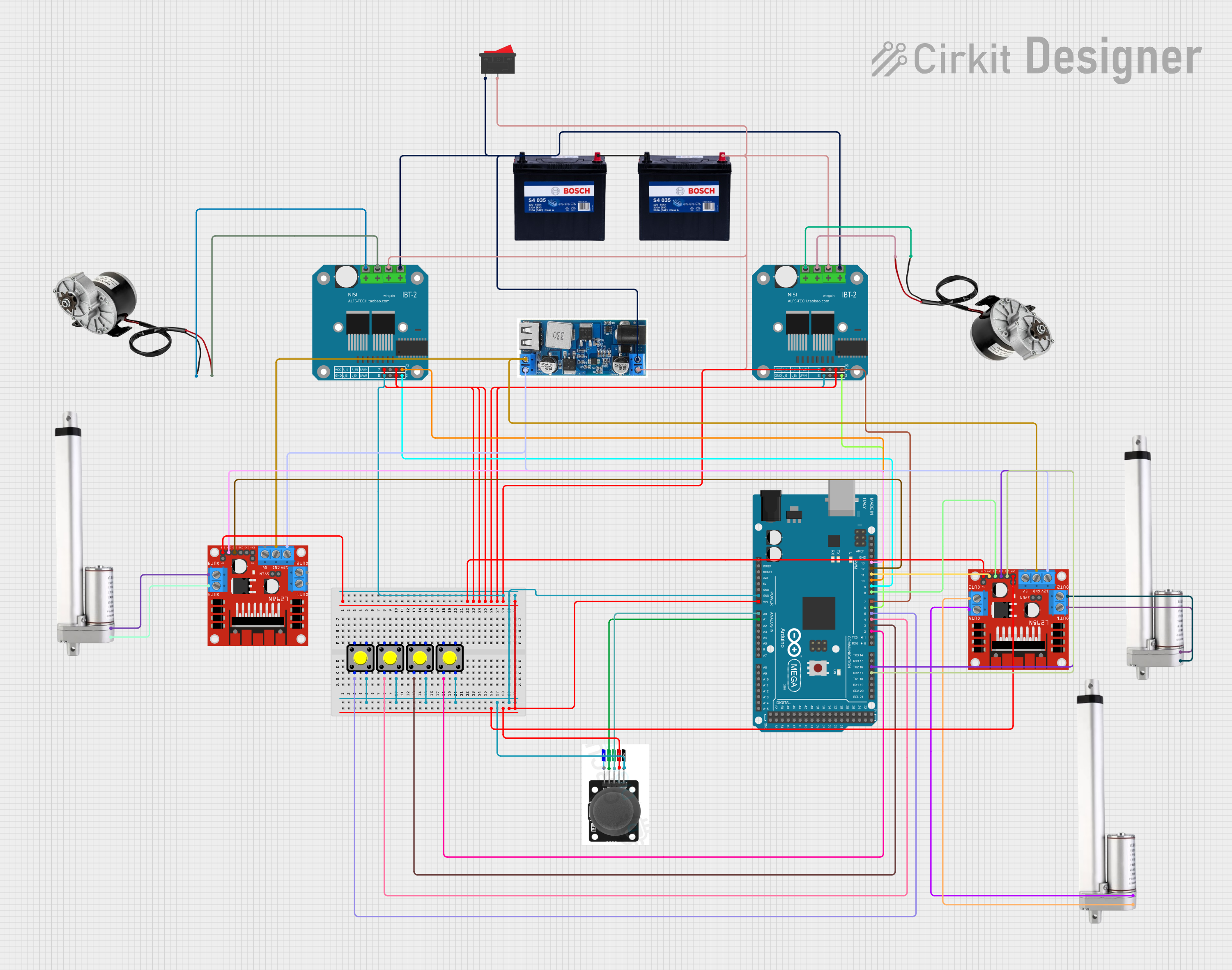 Open Project in Cirkit Designer
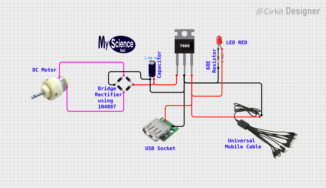 Open Project in Cirkit Designer
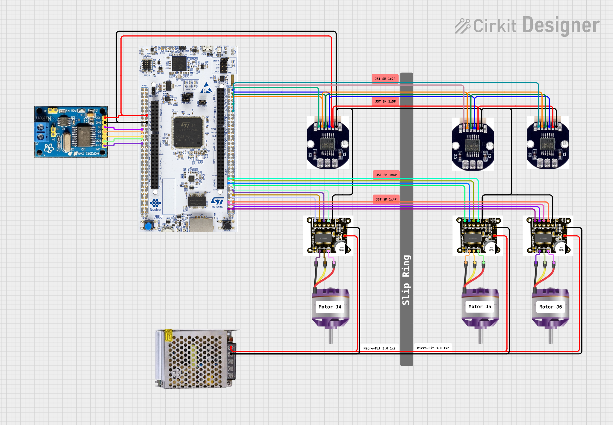 Open Project in Cirkit Designer
Explore Projects Built with Generic Brushed DC Motor
Open Project in Cirkit DesignerOpen Project in Cirkit DesignerOpen Project in Cirkit DesignerOpen Project in Cirkit DesignerCommon Applications and Use Cases
- Robotics: Driving wheels, arms, or other moving parts.
- Automotive: Powering windshield wipers, electric windows, and fans.
- Industrial: Conveyor belts, pumps, and small machinery.
- Consumer Electronics: Toys, small appliances, and hobby projects.
Technical Specifications
Below are the general specifications for a typical Generic Brushed DC Motor. Note that actual values may vary depending on the specific model.
| Parameter | Value |
|---|---|
| Operating Voltage | 3V to 12V DC |
| Rated Current | 0.5A to 2A |
| Stall Current | 2A to 5A |
| Rated Speed | 1000 to 5000 RPM |
| Torque | 0.1 to 1 Nm |
| Power Output | 1W to 30W |
| Motor Type | Brushed DC |
| Shaft Diameter | 2mm to 6mm |
| Dimensions | Varies (e.g., 25mm x 20mm x 15mm) |
Pin Configuration and Descriptions
Brushed DC motors typically have two terminals for electrical connections:
| Pin/Terminal | Description |
|---|---|
| Positive (+) | Connect to the positive terminal of the power supply. |
| Negative (-) | Connect to the negative terminal of the power supply. |
Usage Instructions
How to Use the Component in a Circuit
- Power Supply: Ensure the motor is powered within its operating voltage range (e.g., 3V to 12V DC). Exceeding this range may damage the motor.
- Motor Driver: Use a motor driver (e.g., L298N or L293D) or an H-bridge circuit to control the motor. Directly connecting the motor to a microcontroller is not recommended due to high current requirements.
- Connections:
- Connect the motor terminals to the output pins of the motor driver.
- Connect the motor driver input pins to the control signals from a microcontroller (e.g., Arduino).
- Control: Use Pulse Width Modulation (PWM) to control the motor speed. Adjust the duty cycle of the PWM signal to vary the speed.
Important Considerations and Best Practices
- Current Limiting: Use a motor driver or current-limiting resistor to prevent excessive current draw.
- Heat Dissipation: Ensure proper ventilation or heat sinks to avoid overheating during prolonged use.
- Reverse Polarity: Avoid reversing the polarity of the power supply, as it may damage the motor.
- Noise Suppression: Add capacitors (e.g., 0.1µF) across the motor terminals to reduce electrical noise.
- Load: Avoid overloading the motor beyond its rated torque to prevent stalling or damage.
Example: Controlling a Brushed DC Motor with Arduino UNO
Below is an example of how to control a brushed DC motor using an Arduino UNO and an L298N motor driver.
// Define motor control pins
const int ENA = 9;  // PWM pin for speed control
const int IN1 = 8;  // Direction control pin 1
const int IN2 = 7;  // Direction control pin 2

void setup() {
  // Set motor control pins as outputs
  pinMode(ENA, OUTPUT);
  pinMode(IN1, OUTPUT);
  pinMode(IN2, OUTPUT);
}

void loop() {
  // Rotate motor in forward direction
  digitalWrite(IN1, HIGH);  // Set IN1 high
  digitalWrite(IN2, LOW);   // Set IN2 low
  analogWrite(ENA, 128);    // Set speed (0-255, 128 = 50% duty cycle)
  delay(2000);              // Run for 2 seconds

  // Stop the motor
  digitalWrite(IN1, LOW);   // Set IN1 low
  digitalWrite(IN2, LOW);   // Set IN2 low
  delay(1000);              // Wait for 1 second

  // Rotate motor in reverse direction
  digitalWrite(IN1, LOW);   // Set IN1 low
  digitalWrite(IN2, HIGH);  // Set IN2 high
  analogWrite(ENA, 128);    // Set speed (0-255, 128 = 50% duty cycle)
  delay(2000);              // Run for 2 seconds

  // Stop the motor
  digitalWrite(IN1, LOW);   // Set IN1 low
  digitalWrite(IN2, LOW);   // Set IN2 low
  delay(1000);              // Wait for 1 second
}
Troubleshooting and FAQs
Common Issues and Solutions
Motor Does Not Spin:
- Check the power supply voltage and current. Ensure it meets the motor's requirements.
- Verify the connections to the motor driver and microcontroller.
- Ensure the motor driver is functioning correctly.
Motor Spins in the Wrong Direction:
- Reverse the connections to the motor terminals or adjust the control signals (e.g., IN1 and IN2).
Motor Overheats:
- Reduce the load on the motor.
- Ensure proper ventilation or add a heat sink.
Excessive Noise or Interference:
- Add capacitors (e.g., 0.1µF) across the motor terminals to suppress electrical noise.
- Use shielded cables for connections.
Motor Stalls Under Load:
- Check if the load exceeds the motor's rated torque.
- Use a motor with higher torque or reduce the load.
FAQs
Q: Can I connect a brushed DC motor directly to an Arduino?
A: No, Arduino pins cannot supply the high current required by the motor. Use a motor driver or H-bridge circuit.
Q: How do I control the speed of the motor?
A: Use PWM (Pulse Width Modulation) to control the motor speed. Adjust the duty cycle of the PWM signal.
Q: Can I run the motor in both directions?
A: Yes, by using an H-bridge or motor driver, you can control the direction of rotation.
Q: What happens if I exceed the motor's voltage rating?
A: Exceeding the voltage rating may damage the motor or reduce its lifespan. Always operate within the specified voltage range.