How to Use Velleman Experiment board K8055N: Examples, Pinouts, and Specs
Introduction
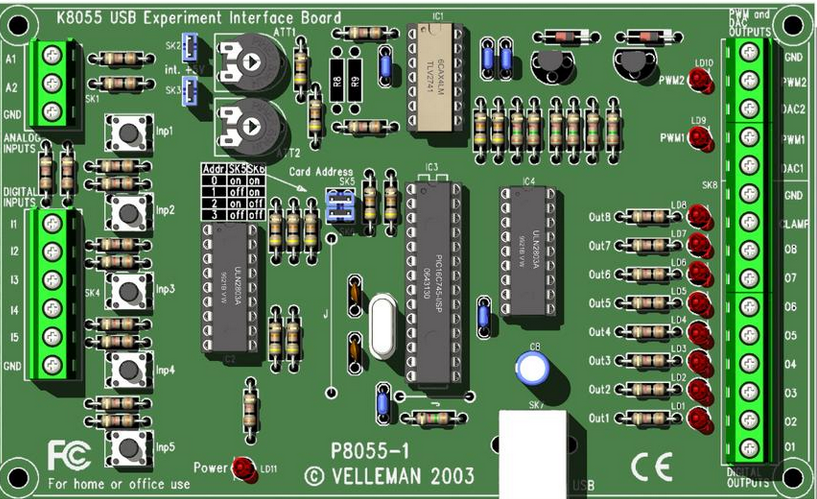
The Velleman Experiment Board K8055N is a versatile USB interface board designed for educational and experimental purposes. It allows users to control and monitor various electronic components and sensors through a computer. The board is ideal for hobbyists, students, and professionals who want to explore the basics of interfacing hardware with software.
Explore Projects Built with Velleman Experiment board K8055N
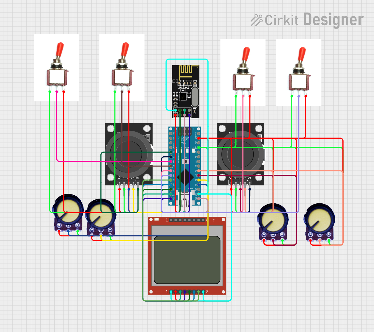
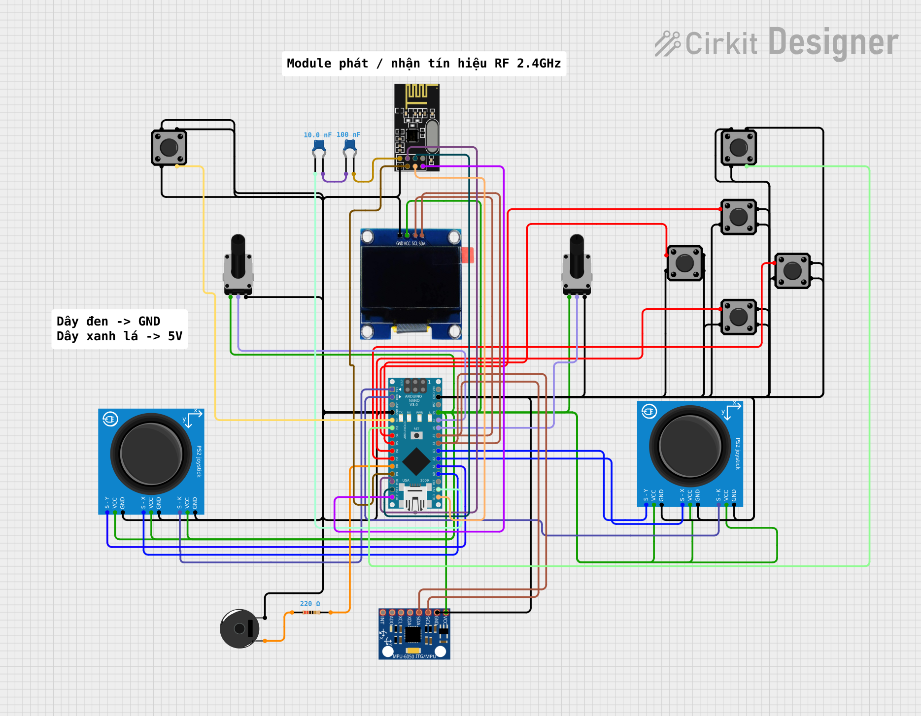
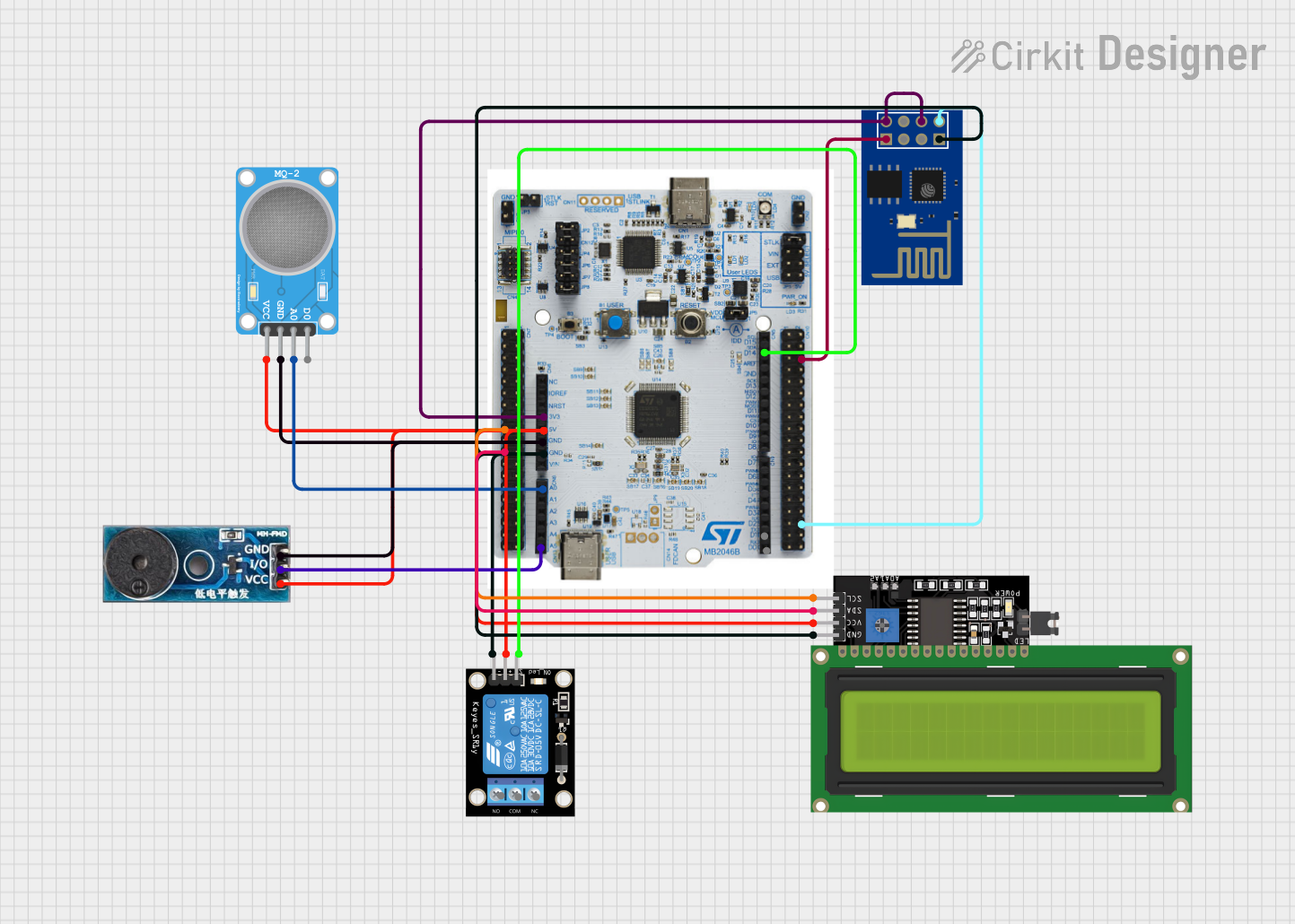
Explore Projects Built with Velleman Experiment board K8055N
Common Applications and Use Cases
- Educational projects for learning USB interfacing
- Controlling relays, LEDs, and other output devices
- Monitoring analog and digital sensors
- Prototyping and testing electronic circuits
- Home automation and custom control systems
Technical Specifications
The K8055N board is equipped with a range of features that make it suitable for a variety of applications. Below are the key technical details:
Key Technical Details
- Power Supply: USB-powered (5V DC)
- Digital Inputs: 5 channels (TTL-level compatible)
- Digital Outputs: 8 open-collector outputs (max 50V/100mA per channel)
- Analog Inputs: 2 channels (10-bit resolution, 0-5V range)
- Analog Outputs: 2 channels (8-bit resolution, 0-5V range)
- Communication Interface: USB 1.1/2.0 compatible
- Supported Operating Systems: Windows (with DLL support for custom applications)
- Dimensions: 145 x 88 x 20 mm
Pin Configuration and Descriptions
The K8055N board has multiple connectors for inputs and outputs. Below is a detailed description of the pin configuration:
Digital Inputs
| Pin Number | Label | Description |
|---|---|---|
| 1 | DI1 | Digital Input 1 |
| 2 | DI2 | Digital Input 2 |
| 3 | DI3 | Digital Input 3 |
| 4 | DI4 | Digital Input 4 |
| 5 | DI5 | Digital Input 5 |
| 6 | GND | Ground for digital inputs |
Digital Outputs
| Pin Number | Label | Description |
|---|---|---|
| 1 | DO1 | Digital Output 1 |
| 2 | DO2 | Digital Output 2 |
| 3 | DO3 | Digital Output 3 |
| 4 | DO4 | Digital Output 4 |
| 5 | DO5 | Digital Output 5 |
| 6 | DO6 | Digital Output 6 |
| 7 | DO7 | Digital Output 7 |
| 8 | DO8 | Digital Output 8 |
Analog Inputs and Outputs
| Pin Number | Label | Description |
|---|---|---|
| 1 | AI1 | Analog Input 1 (0-5V) |
| 2 | AI2 | Analog Input 2 (0-5V) |
| 3 | AO1 | Analog Output 1 (0-5V) |
| 4 | AO2 | Analog Output 2 (0-5V) |
Usage Instructions
The K8055N board is easy to set up and use. Follow the steps below to get started:
Step 1: Install the Required Software
- Download the K8055N software package from the Velleman website.
- Install the drivers and the control software on your computer.
- Ensure the USB cable is connected between the K8055N board and your computer.
Step 2: Connect Inputs and Outputs
- Digital Inputs: Connect switches, sensors, or other TTL-compatible devices to the digital input pins.
- Digital Outputs: Connect LEDs, relays, or other devices to the digital output pins. Note that the outputs are open-collector and require an external pull-up resistor if needed.
- Analog Inputs: Connect analog sensors (e.g., potentiometers or temperature sensors) to the analog input pins.
- Analog Outputs: Use the analog output pins to control devices like motors or dim LEDs.
Step 3: Control the Board via Software
- Use the provided control software to monitor inputs and control outputs.
- For custom applications, use the provided DLL to write your own programs in languages like C++, Python, or Visual Basic.
Important Considerations and Best Practices
- Ensure the total current drawn from the USB port does not exceed 500mA.
- Use external power supplies for high-current devices connected to the outputs.
- Avoid applying voltages higher than 5V to the analog inputs to prevent damage.
- Always connect the ground (GND) of external devices to the GND pin of the K8055N board.
Example Code for Arduino UNO Integration
Although the K8055N is primarily controlled via USB, you can interface it with an Arduino UNO for additional functionality. Below is an example of how to read a digital input from the K8055N and control an LED connected to the Arduino:
// Example: Read digital input from K8055N and control an LED
const int k8055nInputPin = 2; // Arduino pin connected to K8055N digital output
const int ledPin = 13;        // Arduino pin connected to an LED

void setup() {
  pinMode(k8055nInputPin, INPUT); // Set K8055N input pin as input
  pinMode(ledPin, OUTPUT);        // Set LED pin as output
}

void loop() {
  int inputState = digitalRead(k8055nInputPin); // Read state from K8055N
  digitalWrite(ledPin, inputState);            // Set LED state based on input
}
Troubleshooting and FAQs
Common Issues and Solutions
The board is not detected by the computer.
- Ensure the USB cable is properly connected.
- Check if the drivers are installed correctly.
- Try using a different USB port or cable.
Digital outputs are not working.
- Verify that the connected devices are within the output current and voltage limits.
- Check if external pull-up resistors are required for your application.
Analog inputs are not reading correctly.
- Ensure the input voltage is within the 0-5V range.
- Check the connections and the sensor's output.
The control software is not responding.
- Restart the software and reconnect the board.
- Ensure no other applications are using the USB port.
Tips for Troubleshooting
- Use a multimeter to verify voltages and connections.
- Test the board with the provided control software before using custom applications.
- Refer to the Velleman user manual for additional details and support.
By following this documentation, you can effectively use the Velleman Experiment Board K8055N for a wide range of educational and experimental projects.