Cirkit Designer Logo
Cirkit Designer
Your all-in-one circuit design IDE
Home / 
Component Documentation

How to Use GY-AS7343: Examples, Pinouts, and Specs

Image of GY-AS7343
Cirkit Designer LogoDesign with GY-AS7343 in Cirkit Designer

Introduction

The GY-AS7343 is a multi-channel spectral sensor designed to detect light across four distinct channels within the visible and near-infrared spectrum. This sensor is particularly adept at color sensing, ambient light detection, and can be used in a variety of applications such as colorimeters, lighting controls, and health monitoring devices. Its precise spectral sensing capabilities make it a valuable component for projects requiring accurate color and light analysis.

Explore Projects Built with GY-AS7343

Use Cirkit Designer to design, explore, and prototype these projects online. Some projects support real-time simulation. Click "Open Project" to start designing instantly!
Logic Gate Circuit with 7408 AND and 7432 OR ICs
Image of gate: A project utilizing GY-AS7343 in a practical application
This circuit includes a 7408 AND gate IC and a 7432 OR gate IC, both powered by a common VCC and GND connection. The circuit is designed to perform basic logical operations, combining AND and OR gates for digital signal processing.
Cirkit Designer LogoOpen Project in Cirkit Designer
Solar-Powered GSM/GPRS+GPS Tracker with Seeeduino XIAO
Image of SOS System : A project utilizing GY-AS7343 in a practical application
This circuit features an Ai Thinker A9G development board for GSM/GPRS and GPS/BDS connectivity, interfaced with a Seeeduino XIAO microcontroller for control and data processing. A solar cell, coupled with a TP4056 charging module, charges a 3.3V battery, which powers the system through a 3.3V regulator ensuring stable operation. The circuit likely serves for remote data communication and location tracking, with the capability to be powered by renewable energy and interfaced with additional sensors or input devices via the Seeeduino XIAO.
Cirkit Designer LogoOpen Project in Cirkit Designer
Cellular-Enabled IoT Device with Real-Time Clock and Power Management
Image of LRCM PHASE 2 BASIC: A project utilizing GY-AS7343 in a practical application
This circuit features a LilyGo-SIM7000G module for cellular communication and GPS functionality, interfaced with an RTC DS3231 for real-time clock capabilities. It includes voltage sensing through two voltage sensor modules, and uses an 8-channel opto-coupler for isolating different parts of the circuit. Power management is handled by a buck converter connected to a DC power source and batteries, with a fuse for protection and a rocker switch for on/off control. Additionally, there's an LED for indication purposes.
Cirkit Designer LogoOpen Project in Cirkit Designer
Arduino Mega 2560 Based Security System with Fingerprint Authentication and SMS Alerts
Image of Door security system: A project utilizing GY-AS7343 in a practical application
This circuit features an Arduino Mega 2560 microcontroller interfaced with a SIM800L GSM module, two fingerprint scanners, an I2C LCD display, an IR sensor, and a piezo buzzer. Power management is handled by a PowerBoost 1000 Basic Pad USB, a TP4056 charging module, and a Li-ion 18650 battery, with an option to use a Mini AC-DC 110V-230V to 5V 700mA module for direct power supply. The primary functionality appears to be a security system with GSM communication capabilities, biometric access control, and visual/audible feedback.
Cirkit Designer LogoOpen Project in Cirkit Designer

Explore Projects Built with GY-AS7343

Use Cirkit Designer to design, explore, and prototype these projects online. Some projects support real-time simulation. Click "Open Project" to start designing instantly!
Image of gate: A project utilizing GY-AS7343 in a practical application
Logic Gate Circuit with 7408 AND and 7432 OR ICs
This circuit includes a 7408 AND gate IC and a 7432 OR gate IC, both powered by a common VCC and GND connection. The circuit is designed to perform basic logical operations, combining AND and OR gates for digital signal processing.
Cirkit Designer LogoOpen Project in Cirkit Designer
Image of SOS System : A project utilizing GY-AS7343 in a practical application
Solar-Powered GSM/GPRS+GPS Tracker with Seeeduino XIAO
This circuit features an Ai Thinker A9G development board for GSM/GPRS and GPS/BDS connectivity, interfaced with a Seeeduino XIAO microcontroller for control and data processing. A solar cell, coupled with a TP4056 charging module, charges a 3.3V battery, which powers the system through a 3.3V regulator ensuring stable operation. The circuit likely serves for remote data communication and location tracking, with the capability to be powered by renewable energy and interfaced with additional sensors or input devices via the Seeeduino XIAO.
Cirkit Designer LogoOpen Project in Cirkit Designer
Image of LRCM PHASE 2 BASIC: A project utilizing GY-AS7343 in a practical application
Cellular-Enabled IoT Device with Real-Time Clock and Power Management
This circuit features a LilyGo-SIM7000G module for cellular communication and GPS functionality, interfaced with an RTC DS3231 for real-time clock capabilities. It includes voltage sensing through two voltage sensor modules, and uses an 8-channel opto-coupler for isolating different parts of the circuit. Power management is handled by a buck converter connected to a DC power source and batteries, with a fuse for protection and a rocker switch for on/off control. Additionally, there's an LED for indication purposes.
Cirkit Designer LogoOpen Project in Cirkit Designer
Image of Door security system: A project utilizing GY-AS7343 in a practical application
Arduino Mega 2560 Based Security System with Fingerprint Authentication and SMS Alerts
This circuit features an Arduino Mega 2560 microcontroller interfaced with a SIM800L GSM module, two fingerprint scanners, an I2C LCD display, an IR sensor, and a piezo buzzer. Power management is handled by a PowerBoost 1000 Basic Pad USB, a TP4056 charging module, and a Li-ion 18650 battery, with an option to use a Mini AC-DC 110V-230V to 5V 700mA module for direct power supply. The primary functionality appears to be a security system with GSM communication capabilities, biometric access control, and visual/audible feedback.
Cirkit Designer LogoOpen Project in Cirkit Designer

Technical Specifications

Key Technical Details

  • Spectral Range: Visible to near-infrared
  • Number of Channels: 4
  • Interface: I2C
  • Supply Voltage: 3.3V - 5V
  • Operating Current: Typically 5mA
  • Peak Sensitivity Wavelengths: TBD nm (Channel 1), TBD nm (Channel 2), TBD nm (Channel 3), TBD nm (Channel 4)
  • Resolution: 16-bit ADC per channel
  • Response Time: TBD ms

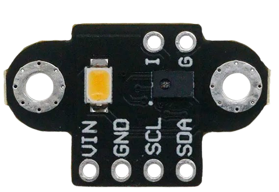
Pin Configuration and Descriptions

Pin Number Pin Name Description
1 VDD Power supply (3.3V - 5V)
2 GND Ground
3 SCL I2C clock signal
4 SDA I2C data signal
5 INT Interrupt (active low)
6 NC No connection (reserved for future use)

Usage Instructions

Integration into a Circuit

To use the GY-AS7343 in a circuit:

  1. Connect the VDD pin to a 3.3V or 5V power supply.
  2. Connect the GND pin to the ground of the power supply.
  3. Interface the SCL and SDA pins with the I2C bus of a microcontroller, such as an Arduino UNO.
  4. Optionally, connect the INT pin to a digital input on the microcontroller if interrupt-driven measurements are required.

Best Practices

  • Ensure that the power supply is stable and within the specified voltage range.
  • Use pull-up resistors on the I2C lines (SCL and SDA) if they are not already present on the microcontroller board.
  • Avoid placing the sensor in direct sunlight or near strong light sources that could saturate the sensor.
  • Calibrate the sensor for the specific application to ensure accurate readings.

Example Code for Arduino UNO

#include <Wire.h>

// GY-AS7343 I2C address (check datasheet for your device's address)
#define AS7343_ADDRESS 0x39

void setup() {
  Wire.begin(); // Initialize I2C
  Serial.begin(9600); // Start serial communication at 9600 baud rate

  // Configure sensor (pseudo-code, replace with actual configuration)
  writeRegister(AS7343_ADDRESS, CONFIG_REGISTER, CONFIG_SETTINGS);
}

void loop() {
  // Read sensor data (pseudo-code, replace with actual read commands)
  uint16_t channel1 = readChannel(AS7343_ADDRESS, CHANNEL1_REGISTER);
  uint16_t channel2 = readChannel(AS7343_ADDRESS, CHANNEL2_REGISTER);
  uint16_t channel3 = readChannel(AS7343_ADDRESS, CHANNEL3_REGISTER);
  uint16_t channel4 = readChannel(AS7343_ADDRESS, CHANNEL4_REGISTER);

  // Output the readings to the serial monitor
  Serial.print("Channel 1: "); Serial.println(channel1);
  Serial.print("Channel 2: "); Serial.println(channel2);
  Serial.print("Channel 3: "); Serial.println(channel3);
  Serial.print("Channel 4: "); Serial.println(channel4);

  delay(1000); // Wait for 1 second before reading again
}

// Function to write a value to a register (pseudo-code)
void writeRegister(byte address, byte reg, byte value) {
  Wire.beginTransmission(address);
  Wire.write(reg);
  Wire.write(value);
  Wire.endTransmission();
}

// Function to read a 16-bit value from a register pair (pseudo-code)
uint16_t readChannel(byte address, byte reg) {
  Wire.beginTransmission(address);
  Wire.write(reg);
  Wire.endTransmission(false);
  Wire.requestFrom(address, (byte)2);

  uint16_t reading = Wire.read();
  reading |= Wire.read() << 8;

  return reading;
}

Please note that the above code is a template and does not contain actual register addresses or configuration settings. Refer to the GY-AS7343 datasheet for specific commands and register addresses.

Troubleshooting and FAQs

Common Issues

  • Sensor Not Responding: Ensure that the sensor is correctly powered and that the I2C connections are secure. Check for proper pull-up resistors on the I2C lines.
  • Inaccurate Readings: Calibrate the sensor for the light conditions of your application. Verify that the sensor is not exposed to saturating light levels.

FAQs

Q: Can the GY-AS7343 be used with a 5V microcontroller like the Arduino UNO? A: Yes, the GY-AS7343 can be interfaced with a 5V microcontroller, provided that the logic levels are compatible or level shifting is used.

Q: How can I calibrate the sensor for accurate color detection? A: Calibration involves taking readings under known light conditions and adjusting the readings based on known reference values. This process can be complex and may require specialized equipment.

Q: What is the purpose of the INT pin? A: The INT pin can be used to trigger an interrupt on the microcontroller when a measurement is ready, allowing for more efficient data collection.

For further assistance, consult the GY-AS7343 datasheet or contact technical support.