How to Use 128x32 OLED: Examples, Pinouts, and Specs
Introduction
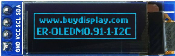
The 128x32 OLED Display Module (Manufacturer Part ID: 0.91-inch 128x32 IIC/I2C Blue OLED Display Module) is a compact, low-power display designed for use in embedded systems. It features a resolution of 128x32 pixels and uses OLED (Organic Light Emitting Diode) technology, which provides high contrast, wide viewing angles, and low power consumption. The module communicates via the I2C (Inter-Integrated Circuit) protocol, making it easy to interface with microcontrollers such as Arduino, Raspberry Pi, and other development boards.
Explore Projects Built with 128x32 OLED


Explore Projects Built with 128x32 OLED
Common Applications
- Displaying text, icons, or simple graphics in embedded systems
- Wearable devices and IoT (Internet of Things) projects
- Battery-powered devices due to its low power consumption
- Debugging and status monitoring in microcontroller-based systems
Technical Specifications
The following table outlines the key technical details of the 128x32 OLED Display Module:
| Parameter | Specification |
|---|---|
| Display Type | OLED (Organic Light Emitting Diode) |
| Resolution | 128x32 pixels |
| Communication Protocol | I2C (IIC) |
| Operating Voltage | 3.3V to 5V |
| Operating Current | ~20mA (typical) |
| Viewing Angle | >160° |
| Display Color | Blue |
| Dimensions | 0.91 inches (diagonal) |
| Driver IC | SSD1306 |
Pin Configuration
The module typically has a 4-pin interface for I2C communication. The pinout is as follows:
| Pin | Name | Description |
|---|---|---|
| 1 | GND | Ground (0V) |
| 2 | VCC | Power supply (3.3V to 5V) |
| 3 | SCL | Serial Clock Line for I2C communication |
| 4 | SDA | Serial Data Line for I2C communication |
Usage Instructions
Connecting the OLED to an Arduino UNO
To use the 128x32 OLED with an Arduino UNO, follow these steps:
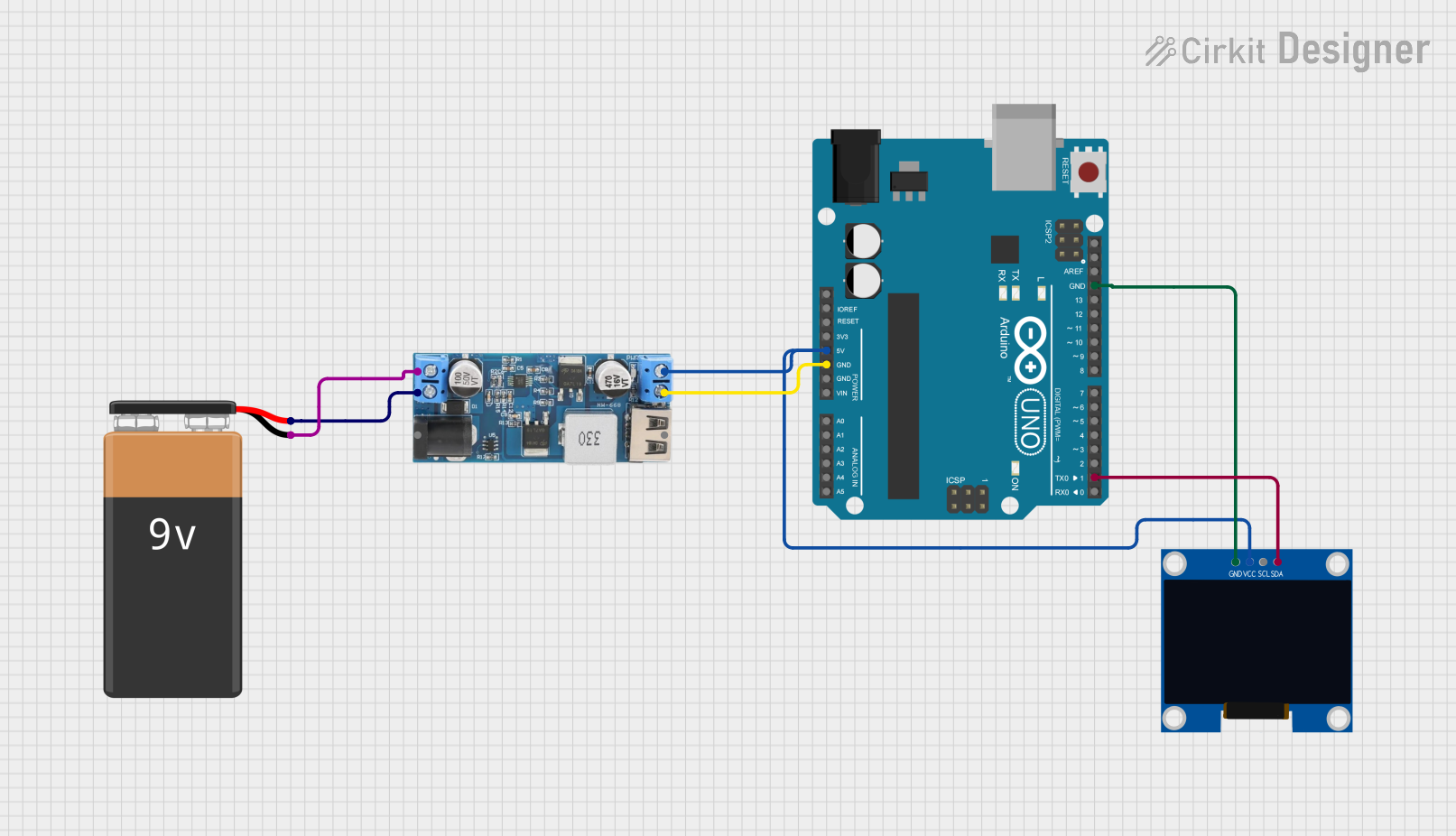
- Wiring: Connect the OLED module to the Arduino as shown below:
- GND → GND
- VCC → 5V
- SCL → A5 (I2C Clock)
- SDA → A4 (I2C Data)
- Install Libraries: Install the required libraries in the Arduino IDE:
- Go to Sketch > Include Library > Manage Libraries.
- Search for and install the following libraries:
Adafruit GFX LibraryAdafruit SSD1306
- Upload Code: Use the example code below to display text on the OLED.
Example Code
#include <Wire.h>
#include <Adafruit_GFX.h>
#include <Adafruit_SSD1306.h>

// Define the OLED display width and height
#define SCREEN_WIDTH 128
#define SCREEN_HEIGHT 32

// Create an SSD1306 display object (I2C address is typically 0x3C)
Adafruit_SSD1306 display(SCREEN_WIDTH, SCREEN_HEIGHT, &Wire, -1);

void setup() {
  // Initialize the display
  if (!display.begin(SSD1306_I2C_ADDRESS, 0x3C)) {
    // If initialization fails, print an error message
    Serial.println(F("SSD1306 allocation failed"));
    for (;;); // Halt execution
  }

  // Clear the display buffer
  display.clearDisplay();

  // Set text size and color
  display.setTextSize(1); // Text size multiplier
  display.setTextColor(SSD1306_WHITE);

  // Display a message
  display.setCursor(0, 0); // Set cursor to top-left corner
  display.println(F("Hello, OLED!"));
  display.display(); // Render the text on the screen
}

void loop() {
  // No actions in the loop for this example
}
Important Considerations
- I2C Address: The default I2C address for most 128x32 OLED modules is
0x3C. If the display does not work, verify the address using an I2C scanner sketch. - Power Supply: Ensure the module is powered within its operating voltage range (3.3V to 5V). Exceeding this range may damage the display.
- Library Compatibility: Use the latest versions of the
Adafruit GFXandAdafruit SSD1306libraries for optimal performance.
Troubleshooting and FAQs
Common Issues
The display does not turn on:
- Verify the wiring connections, especially GND and VCC.
- Ensure the power supply voltage is within the specified range (3.3V to 5V).
- Check if the I2C address (
0x3C) matches the module's configuration.
Text or graphics do not appear:
- Confirm that the required libraries (
Adafruit GFXandAdafruit SSD1306) are installed. - Ensure the correct I2C pins (SCL and SDA) are connected to the microcontroller.
- Use an I2C scanner sketch to detect the module's address.
- Confirm that the required libraries (
Flickering or unstable display:
- Check for loose connections in the wiring.
- Ensure the power supply can provide sufficient current (~20mA).
FAQs
Q: Can I use this module with a 3.3V microcontroller?
A: Yes, the module supports both 3.3V and 5V logic levels, making it compatible with a wide range of microcontrollers.
Q: How do I display custom graphics?
A: You can use the Adafruit GFX library to draw shapes, lines, and bitmaps. Refer to the library documentation for detailed instructions.
Q: What is the maximum refresh rate of the display?
A: The refresh rate depends on the I2C communication speed and the complexity of the graphics being rendered. For most applications, the default I2C speed (100kHz) is sufficient.
Q: Can I use multiple OLED displays on the same I2C bus?
A: Yes, but each display must have a unique I2C address. Some modules allow you to change the address by soldering jumpers on the back of the PCB.
By following this documentation, you can effectively integrate the 128x32 OLED Display Module into your projects and troubleshoot common issues.