Cirkit Designer Logo
Cirkit Designer
Your all-in-one circuit design IDE
Home / 
Component Documentation

How to Use BRIDGE - 1N4007: Examples, Pinouts, and Specs

Image of BRIDGE - 1N4007
Cirkit Designer LogoDesign with BRIDGE - 1N4007 in Cirkit Designer

Introduction

The 1N4007 is a silicon rectifier diode commonly used for converting alternating current (AC) to direct current (DC). It is a robust and reliable component with a maximum reverse voltage rating of 1000V and a forward current rating of 1A. These characteristics make it ideal for use in power supply circuits, rectifier bridges, and other applications requiring AC-to-DC conversion.

Explore Projects Built with BRIDGE - 1N4007

Use Cirkit Designer to design, explore, and prototype these projects online. Some projects support real-time simulation. Click "Open Project" to start designing instantly!
NPN Transistor-Based Signal Interface with Relimate Connectors
Image of Mini cross: A project utilizing BRIDGE - 1N4007 in a practical application
This circuit appears to be a simple transistor-based switching circuit with multiple NPN transistors and resistors, interfaced through relimate connectors. The transistors are likely used to control the flow of current through various parts of the circuit, possibly for switching or amplification purposes, with the relimate connectors providing external connections for power and signal lines.
Cirkit Designer LogoOpen Project in Cirkit Designer
LED Array with Push Switch Control and Voltage Regulation
Image of Transformer safty device complete: A project utilizing BRIDGE - 1N4007 in a practical application
This circuit is a power supply and control system that steps down 220V AC to 24V AC using a transformer, rectifies it to DC using a bridge rectifier, and regulates it to 5V DC. It includes multiple LEDs controlled by push switches and a relay, with a capacitor for smoothing the output.
Cirkit Designer LogoOpen Project in Cirkit Designer
Piezo Sensor-Based LED Indicator with Pushbutton Control
Image of project: A project utilizing BRIDGE - 1N4007 in a practical application
This circuit is a rectifier and indicator system that uses multiple 1N4007 diodes to rectify an AC signal, a piezo sensor for signal detection, and a pushbutton to control the circuit. The rectified signal is filtered by an electrolytic capacitor and a resistor, and the presence of the signal is indicated by a blue LED.
Cirkit Designer LogoOpen Project in Cirkit Designer
AC to DC Power Supply with Voltage Regulation and LED Indicator
Image of Copy of 8 volt AC to DC convertor (1): A project utilizing BRIDGE - 1N4007 in a practical application
This circuit is a basic AC to DC power supply with voltage regulation. It includes a transformer to step down the AC voltage, a bridge rectifier made of 1N4007 diodes to convert AC to DC, an electrolytic capacitor for smoothing, and a voltage regulator to provide a stable DC output. An LED with a current-limiting resistor indicates the presence of the output voltage.
Cirkit Designer LogoOpen Project in Cirkit Designer

Explore Projects Built with BRIDGE - 1N4007

Use Cirkit Designer to design, explore, and prototype these projects online. Some projects support real-time simulation. Click "Open Project" to start designing instantly!
Image of Mini cross: A project utilizing BRIDGE - 1N4007 in a practical application
NPN Transistor-Based Signal Interface with Relimate Connectors
This circuit appears to be a simple transistor-based switching circuit with multiple NPN transistors and resistors, interfaced through relimate connectors. The transistors are likely used to control the flow of current through various parts of the circuit, possibly for switching or amplification purposes, with the relimate connectors providing external connections for power and signal lines.
Cirkit Designer LogoOpen Project in Cirkit Designer
Image of Transformer safty device complete: A project utilizing BRIDGE - 1N4007 in a practical application
LED Array with Push Switch Control and Voltage Regulation
This circuit is a power supply and control system that steps down 220V AC to 24V AC using a transformer, rectifies it to DC using a bridge rectifier, and regulates it to 5V DC. It includes multiple LEDs controlled by push switches and a relay, with a capacitor for smoothing the output.
Cirkit Designer LogoOpen Project in Cirkit Designer
Image of project: A project utilizing BRIDGE - 1N4007 in a practical application
Piezo Sensor-Based LED Indicator with Pushbutton Control
This circuit is a rectifier and indicator system that uses multiple 1N4007 diodes to rectify an AC signal, a piezo sensor for signal detection, and a pushbutton to control the circuit. The rectified signal is filtered by an electrolytic capacitor and a resistor, and the presence of the signal is indicated by a blue LED.
Cirkit Designer LogoOpen Project in Cirkit Designer
Image of Copy of 8 volt AC to DC convertor (1): A project utilizing BRIDGE - 1N4007 in a practical application
AC to DC Power Supply with Voltage Regulation and LED Indicator
This circuit is a basic AC to DC power supply with voltage regulation. It includes a transformer to step down the AC voltage, a bridge rectifier made of 1N4007 diodes to convert AC to DC, an electrolytic capacitor for smoothing, and a voltage regulator to provide a stable DC output. An LED with a current-limiting resistor indicates the presence of the output voltage.
Cirkit Designer LogoOpen Project in Cirkit Designer

Common Applications and Use Cases

  • Power supply rectification (AC to DC conversion)
  • Protection circuits (e.g., flyback diodes in inductive loads)
  • Voltage clamping and polarity protection
  • General-purpose rectification in low- to medium-power circuits

Technical Specifications

The 1N4007 diode is designed to handle high voltages and currents in a compact package. Below are its key technical specifications:

Parameter Value
Maximum Reverse Voltage 1000V
Maximum Forward Current 1A
Peak Surge Current 30A (8.3ms single half-sine)
Forward Voltage Drop 0.7V (typical at 1A)
Reverse Recovery Time 2µs
Operating Temperature -55°C to +150°C
Package Type DO-41

Pin Configuration and Descriptions

The 1N4007 is a two-terminal device with the following pin configuration:

Pin Name Description
1 Anode (+) Positive terminal; current flows into this terminal.
2 Cathode (-) Negative terminal; current flows out of this terminal.

The cathode is typically marked with a silver or white band on the diode body.

Usage Instructions

The 1N4007 diode is straightforward to use in circuits. Below are the steps and considerations for its proper usage:

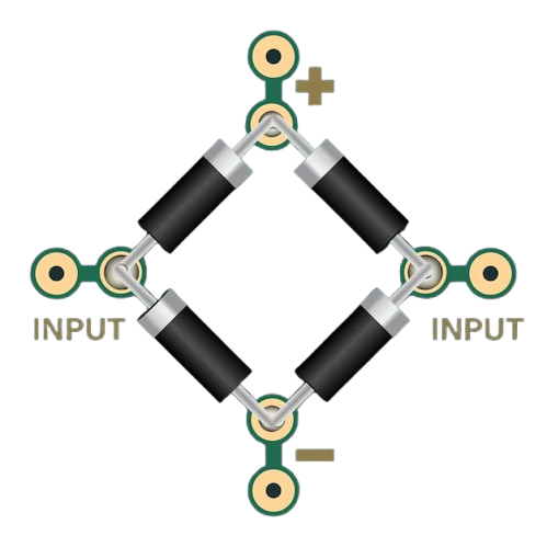
Using the 1N4007 in a Rectifier Bridge

To create a full-wave rectifier bridge, you will need four 1N4007 diodes. Connect them as follows:

  1. Arrange the diodes in a diamond configuration.
  2. Connect the AC input to the two opposite corners of the diamond.
  3. The remaining two corners will serve as the DC output (positive and negative terminals).

Important Considerations

  • Polarity: Ensure the diode is connected with the correct polarity. The anode should be connected to the positive side of the circuit, and the cathode to the negative side.
  • Voltage and Current Ratings: Do not exceed the maximum reverse voltage (1000V) or forward current (1A) ratings to avoid damaging the diode.
  • Heat Dissipation: If the diode operates near its maximum current rating, consider adding a heatsink or ensuring proper ventilation to prevent overheating.

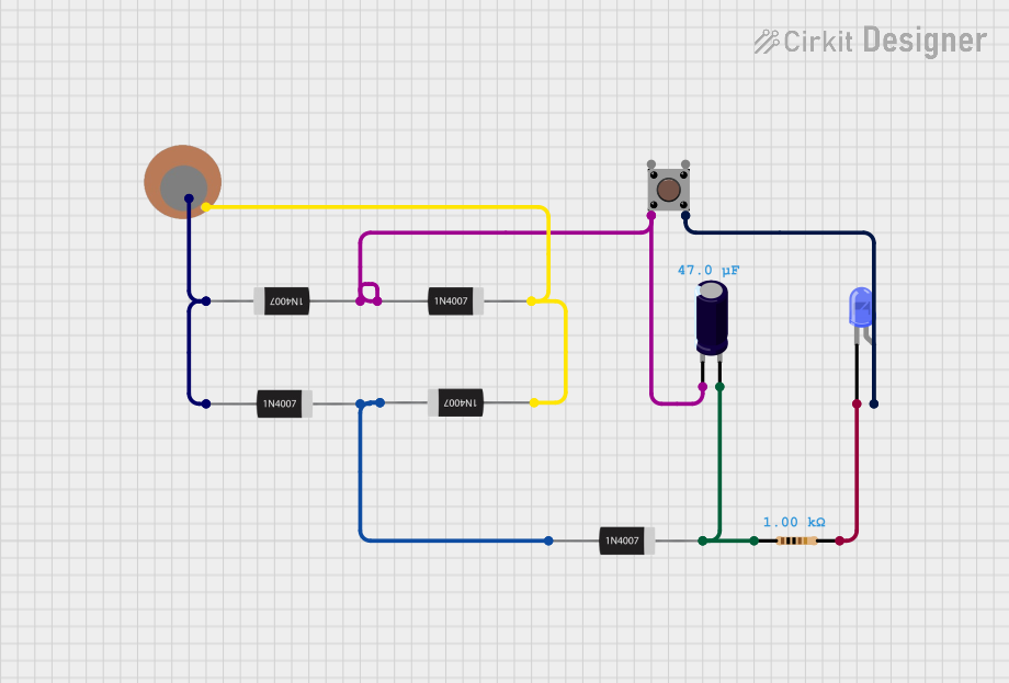
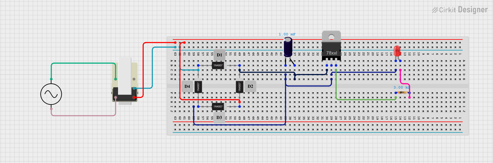
Example: Connecting a 1N4007 Bridge to an Arduino UNO

The 1N4007 bridge can be used to power an Arduino UNO from an AC source. Below is an example circuit and code:

Circuit Description

  1. Use four 1N4007 diodes to create a rectifier bridge.
  2. Connect the AC input to the bridge.
  3. Add a smoothing capacitor (e.g., 1000µF, 25V) across the DC output to reduce ripple.
  4. Connect the DC output to the Arduino's VIN and GND pins.

Example Code

// Example code for reading an analog sensor powered by a 1N4007 bridge
// connected to an Arduino UNO. Ensure the bridge provides a stable DC voltage.

const int sensorPin = A0;  // Analog pin connected to the sensor
int sensorValue = 0;       // Variable to store the sensor reading

void setup() {
  Serial.begin(9600);  // Initialize serial communication
}

void loop() {
  sensorValue = analogRead(sensorPin);  // Read the sensor value
  Serial.print("Sensor Value: ");
  Serial.println(sensorValue);  // Print the sensor value to the Serial Monitor
  delay(500);  // Wait for 500ms before the next reading
}

Troubleshooting and FAQs

Common Issues

  1. Diode Overheating:

    • Cause: Exceeding the maximum current rating or insufficient heat dissipation.
    • Solution: Reduce the load current or add a heatsink.
  2. No Output Voltage:

    • Cause: Incorrect diode orientation or damaged diodes.
    • Solution: Verify the polarity of each diode and replace any damaged components.
  3. High Ripple in DC Output:

    • Cause: Insufficient filtering.
    • Solution: Add a larger smoothing capacitor or use a voltage regulator.

FAQs

Q: Can I use the 1N4007 for high-frequency applications?
A: No, the 1N4007 is not suitable for high-frequency applications due to its relatively slow reverse recovery time (2µs). Use a fast-recovery or Schottky diode for such applications.

Q: What happens if I exceed the reverse voltage rating?
A: Exceeding the reverse voltage rating (1000V) can cause the diode to break down and fail permanently.

Q: Can I use the 1N4007 in a DC circuit?
A: Yes, the 1N4007 can be used in DC circuits for polarity protection or voltage clamping.

By following these guidelines and best practices, you can effectively use the 1N4007 diode in your electronic projects.