How to Use MPPT SCC: Examples, Pinouts, and Specs
Introduction
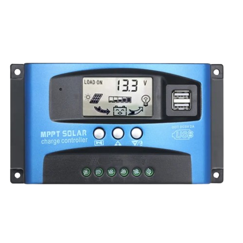
The Maximum Power Point Tracking Solar Charge Controller (MPPT SCC) is an advanced electronic device designed to optimize the power output from solar panels. By dynamically adjusting the electrical operating point of the solar modules, the MPPT SCC ensures maximum energy harvest under varying environmental conditions, such as changes in sunlight intensity and temperature. It also regulates the charging of batteries, ensuring efficient energy storage and prolonging battery life.
Explore Projects Built with MPPT SCC
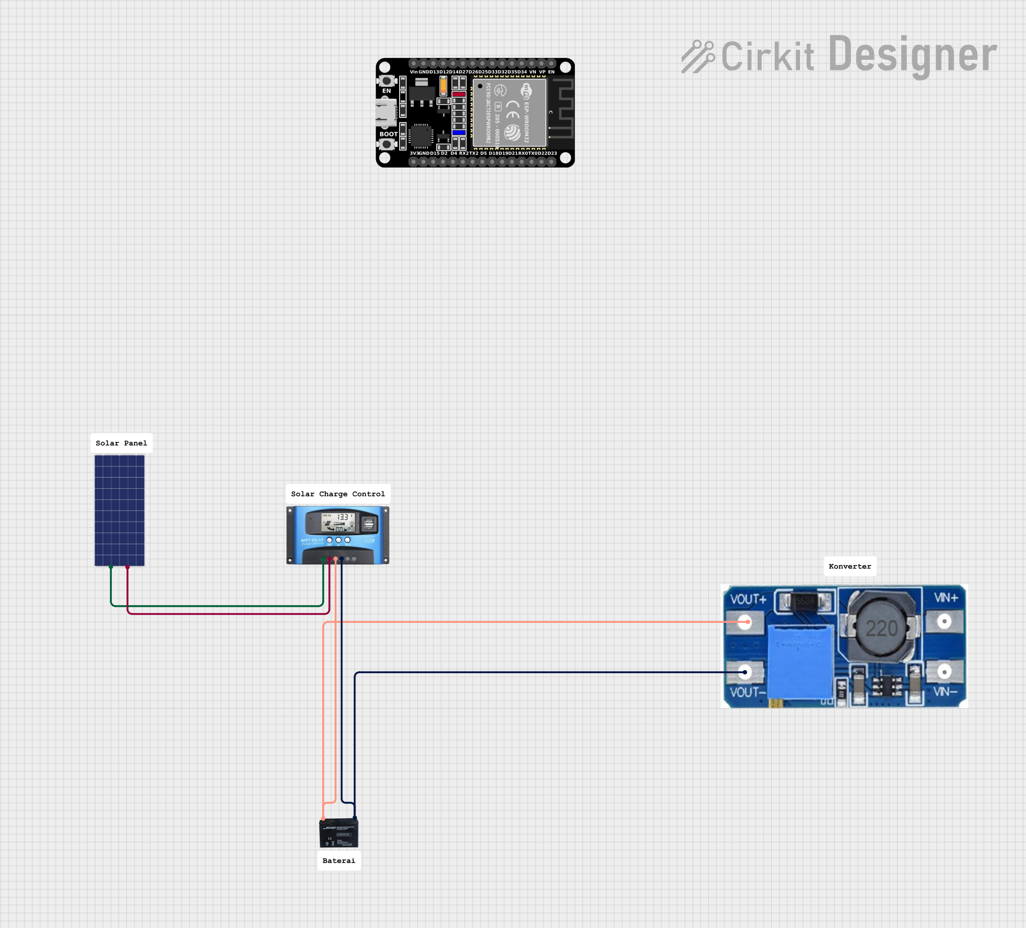
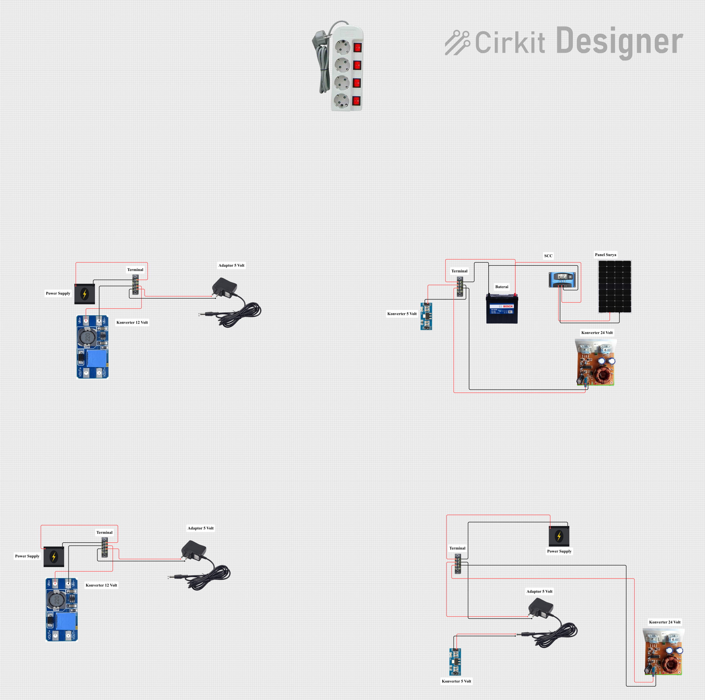
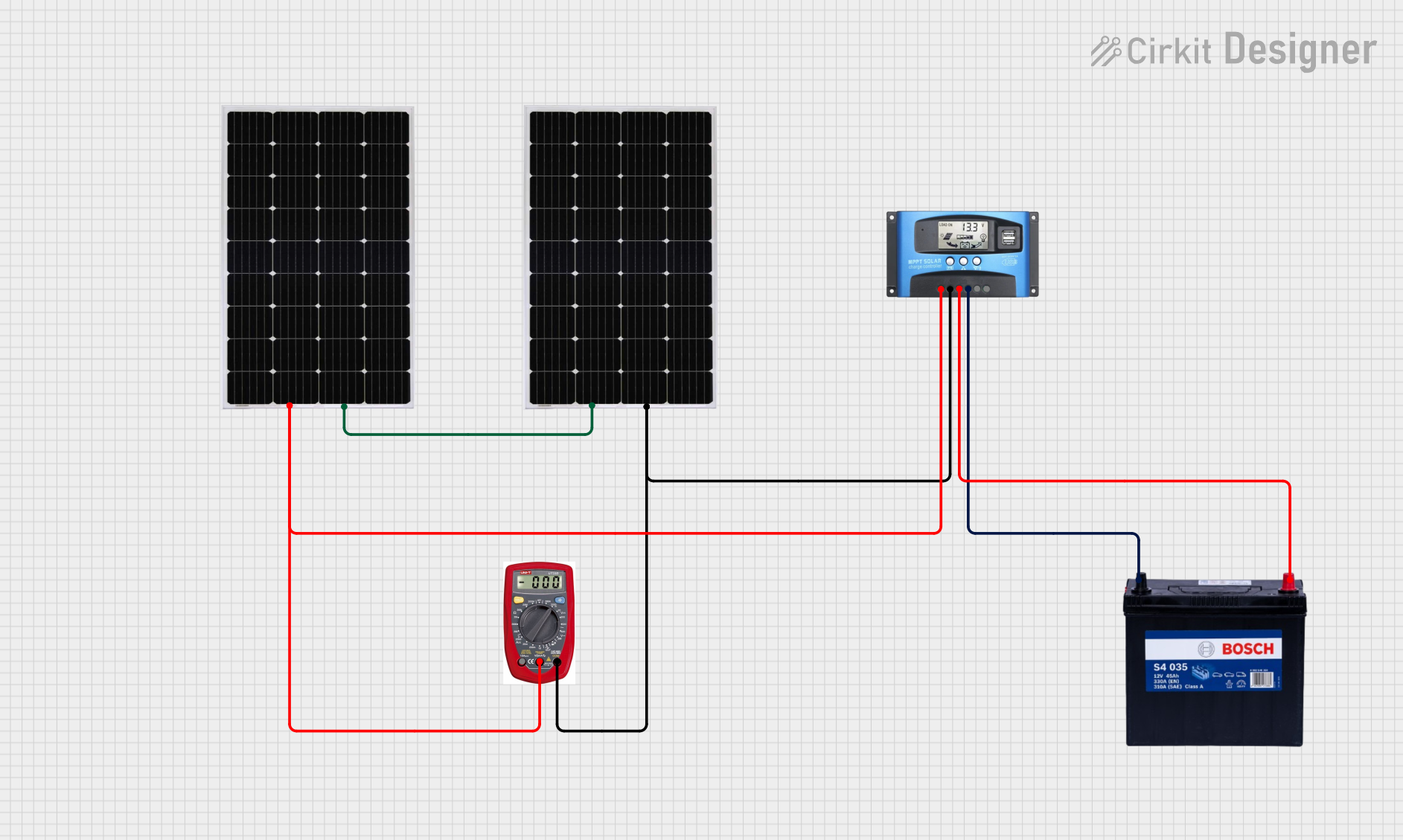
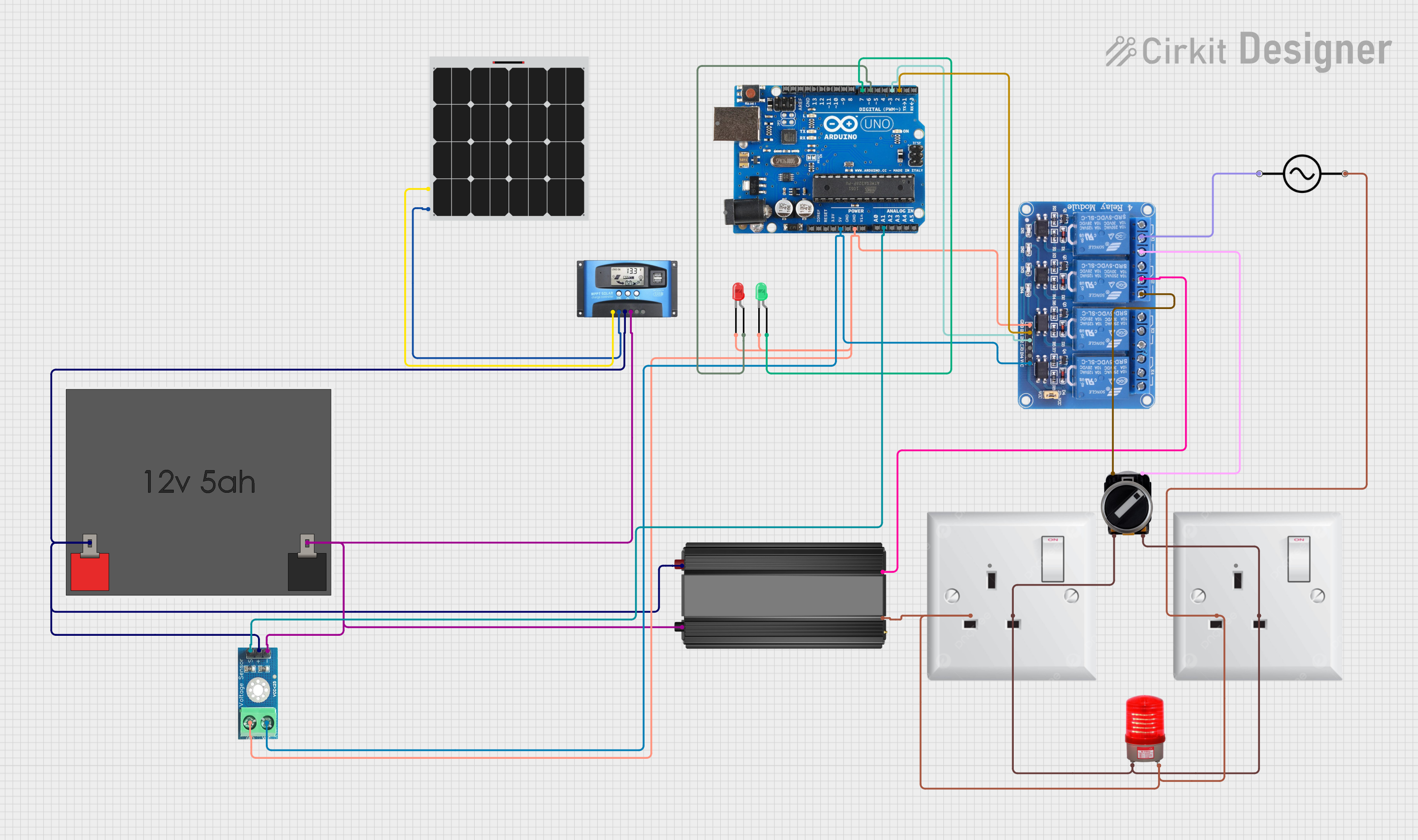
Explore Projects Built with MPPT SCC
Common Applications and Use Cases
- Solar power systems for residential, commercial, and industrial applications
- Off-grid solar installations
- Solar-powered water pumps
- Recreational vehicles (RVs) and marine solar systems
- Backup power systems with battery storage
Technical Specifications
Key Technical Details
| Parameter | Value/Range |
|---|---|
| Input Voltage Range | 12V to 150V DC (varies by model) |
| Output Voltage Range | 12V, 24V, or 48V DC (auto-select) |
| Maximum Input Power | 100W to 3000W (model-dependent) |
| Maximum Efficiency | Up to 98% |
| Battery Type Compatibility | Lead-acid, AGM, Gel, Lithium-ion |
| Operating Temperature | -20°C to 60°C |
| Communication Interfaces | RS485, CAN, Bluetooth (optional) |
| Protections | Overvoltage, overcurrent, short-circuit, reverse polarity |
Pin Configuration and Descriptions
| Pin/Terminal Name | Description |
|---|---|
| PV+ | Positive terminal for solar panel input |
| PV- | Negative terminal for solar panel input |
| BAT+ | Positive terminal for battery connection |
| BAT- | Negative terminal for battery connection |
| LOAD+ | Positive terminal for DC load connection |
| LOAD- | Negative terminal for DC load connection |
| RS485+ | Positive terminal for RS485 communication (if supported) |
| RS485- | Negative terminal for RS485 communication (if supported) |
| Temp Sensor | Input for external temperature sensor to monitor battery temperature |
| Ground (GND) | Common ground for the system |
Usage Instructions
How to Use the MPPT SCC in a Circuit
Connect the Solar Panel:
- Attach the positive and negative terminals of the solar panel to the
PV+andPV-inputs of the MPPT SCC. - Ensure the solar panel's voltage and power ratings are within the controller's input range.
- Attach the positive and negative terminals of the solar panel to the
Connect the Battery:
- Connect the battery's positive terminal to
BAT+and the negative terminal toBAT-. - Verify that the battery type is compatible with the MPPT SCC and configure the controller accordingly (if required).
- Connect the battery's positive terminal to
Connect the Load:
- Attach the DC load to the
LOAD+andLOAD-terminals. - Ensure the load does not exceed the controller's output current rating.
- Attach the DC load to the
Optional Connections:
- If supported, connect the RS485 or CAN interface for monitoring and control.
- Attach the temperature sensor to monitor battery temperature and enable temperature-compensated charging.
Power On:
- Once all connections are secure, power on the system. The MPPT SCC will automatically detect the battery voltage and begin optimizing the solar panel's output.
Important Considerations and Best Practices
- Sizing: Ensure the MPPT SCC is appropriately sized for your solar panel array and battery bank.
- Wiring: Use appropriately rated cables to handle the current and minimize voltage drops.
- Ventilation: Install the MPPT SCC in a well-ventilated area to prevent overheating.
- Battery Settings: Configure the controller for the specific battery type to avoid overcharging or undercharging.
- Firmware Updates: If the controller supports firmware updates, keep it updated for optimal performance and new features.
Example Code for Arduino UNO Monitoring (via RS485)
If your MPPT SCC supports RS485 communication, you can use an Arduino UNO to monitor its data. Below is an example code snippet:
#include <ModbusMaster.h> // Include Modbus library for RS485 communication

// Instantiate ModbusMaster object
ModbusMaster node;

void setup() {
  Serial.begin(9600); // Initialize serial communication for debugging
  node.begin(1, Serial); // Set Modbus ID to 1 and use Serial for communication

  // Print initialization message
  Serial.println("MPPT SCC Monitoring Initialized");
}

void loop() {
  uint8_t result;
  uint16_t data;

  // Read battery voltage (example register address: 0x3100)
  result = node.readInputRegisters(0x3100, 1);
  if (result == node.ku8MBSuccess) {
    data = node.getResponseBuffer(0);
    float batteryVoltage = data / 100.0; // Convert to volts
    Serial.print("Battery Voltage: ");
    Serial.print(batteryVoltage);
    Serial.println(" V");
  } else {
    Serial.println("Failed to read battery voltage");
  }

  delay(1000); // Wait 1 second before next reading
}
Notes:
- Replace
0x3100with the correct register address for your MPPT SCC model. - Use an RS485-to-TTL module to connect the MPPT SCC to the Arduino UNO.
Troubleshooting and FAQs
Common Issues and Solutions
No Output from the Controller:
- Cause: Incorrect wiring or insufficient solar panel input.
- Solution: Verify all connections and ensure the solar panel is receiving adequate sunlight.
Battery Not Charging:
- Cause: Incorrect battery type settings or damaged battery.
- Solution: Check the battery type configuration and test the battery with a multimeter.
Overheating:
- Cause: Poor ventilation or excessive load.
- Solution: Install the controller in a well-ventilated area and reduce the load if necessary.
Communication Failure (RS485):
- Cause: Incorrect wiring or baud rate mismatch.
- Solution: Verify the RS485 connections and ensure the baud rate matches the controller's settings.
FAQs
Q: Can I use the MPPT SCC with a wind turbine?
A: No, MPPT SCCs are specifically designed for solar panels. Use a dedicated wind turbine charge controller.Q: How do I update the firmware?
A: Refer to the manufacturer's instructions for firmware updates. Typically, this involves connecting the controller to a computer via USB or a communication interface.Q: What happens if the battery is fully charged?
A: The MPPT SCC will stop charging the battery and may divert excess energy to a load or disconnect the solar panel.Q: Can I connect multiple MPPT SCCs in parallel?
A: Yes, but ensure each controller is independently connected to its own solar panel array and battery bank.
This documentation provides a comprehensive guide to understanding, using, and troubleshooting the MPPT SCC. For further assistance, consult the manufacturer's manual or technical support.