
How to Use NID100: Examples, Pinouts, and Specs
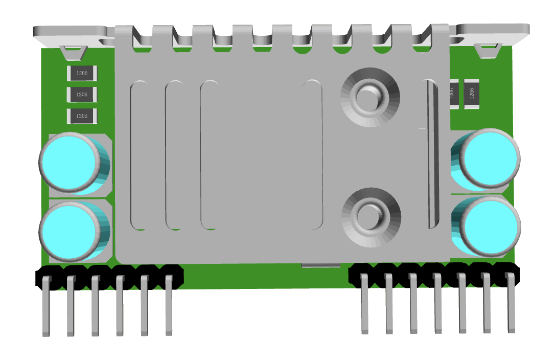
 Design with NID100 in Cirkit Designer
Introduction
The NID100-24 by Mean Well is a network interface device designed to bridge local and external networks. It is commonly used in telecommunications and data transmission systems to ensure reliable connectivity and efficient data management. This device is ideal for applications requiring robust network interfacing, such as industrial automation, IoT systems, and telecommunications infrastructure.
Explore Projects Built with NID100
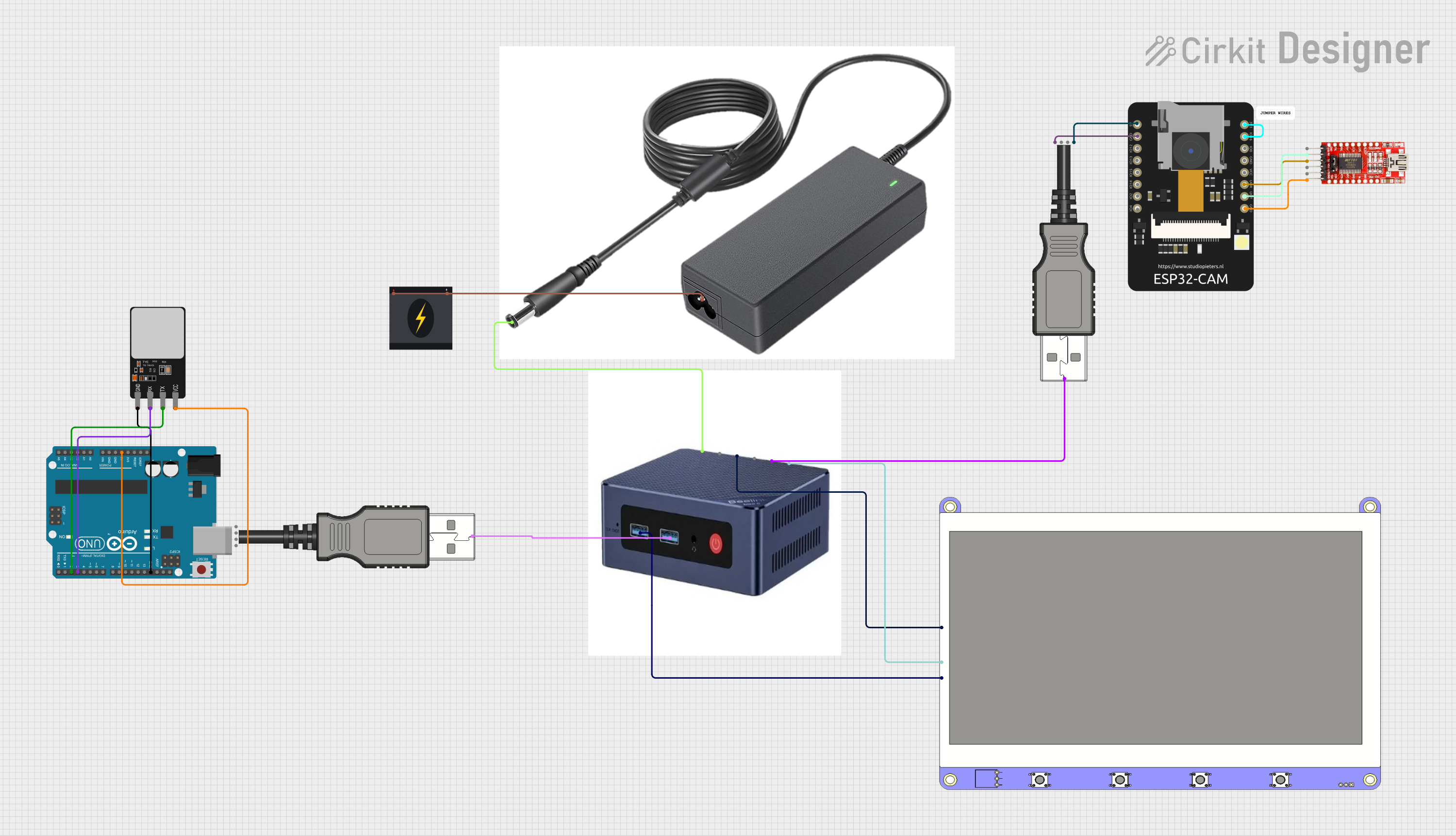 Open Project in Cirkit Designer
 Open Project in Cirkit Designer
 Open Project in Cirkit Designer
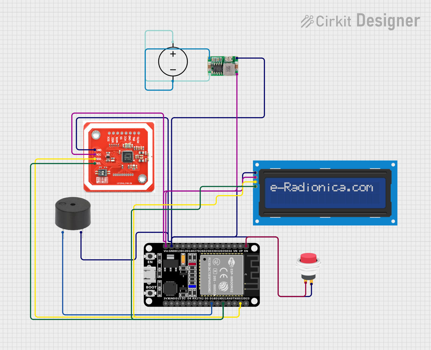 Open Project in Cirkit Designer
Explore Projects Built with NID100
Open Project in Cirkit DesignerOpen Project in Cirkit DesignerOpen Project in Cirkit DesignerOpen Project in Cirkit DesignerCommon Applications:
- Telecommunications systems for managing data transmission
- Industrial automation requiring network interfacing
- IoT (Internet of Things) devices for reliable connectivity
- Data centers and server rooms for network management
- Smart grid and energy management systems
Technical Specifications
Key Technical Details:
| Parameter | Value |
|---|---|
| Manufacturer | Mean Well |
| Part Number | NID100-24 |
| Input Voltage Range | 18–36 VDC |
| Output Voltage | 24 VDC |
| Maximum Output Current | 4.2 A |
| Power Rating | 100 W |
| Efficiency | Up to 92% |
| Operating Temperature | -30°C to +70°C |
| Communication Protocols | Ethernet, TCP/IP |
| Dimensions | 125 x 75 x 30 mm |
| Weight | 300 g |
Pin Configuration and Descriptions:
| Pin Number | Pin Name | Description |
|---|---|---|
| 1 | VIN+ | Positive input voltage terminal (18–36 VDC) |
| 2 | VIN- | Negative input voltage terminal (ground) |
| 3 | VOUT+ | Positive output voltage terminal (24 VDC) |
| 4 | VOUT- | Negative output voltage terminal (ground) |
| 5 | TX+ | Transmit data (positive) for Ethernet communication |
| 6 | TX- | Transmit data (negative) for Ethernet communication |
| 7 | RX+ | Receive data (positive) for Ethernet communication |
| 8 | RX- | Receive data (negative) for Ethernet communication |
| 9 | GND | Ground connection for shielding and safety |
Usage Instructions
How to Use the NID100-24 in a Circuit:
Power Supply Connection:
- Connect the VIN+ and VIN- pins to a DC power source within the range of 18–36 VDC.
- Ensure the power source can supply sufficient current (at least 4.2 A) for the device's operation.
Output Connection:
- Use the VOUT+ and VOUT- pins to power external devices or systems requiring 24 VDC.
Network Connection:
- Connect the TX+, TX-, RX+, and RX- pins to the corresponding Ethernet lines.
- Ensure proper shielding and grounding to minimize interference.
Mounting:
- Secure the NID100-24 in a well-ventilated area to prevent overheating.
- Avoid placing the device near sources of electromagnetic interference.
Important Considerations:
- Voltage Compatibility: Ensure the input voltage is within the specified range (18–36 VDC) to avoid damage.
- Heat Dissipation: Operate the device in an environment with adequate airflow to maintain temperatures within the operating range (-30°C to +70°C).
- Grounding: Proper grounding is essential for safety and to reduce noise in communication lines.
- Ethernet Cable Quality: Use high-quality Ethernet cables to ensure reliable data transmission.
Example: Connecting to an Arduino UNO
The NID100-24 can be used to interface an Arduino UNO with a network. Below is an example of how to send data from the Arduino to a network via the NID100-24.
#include <SPI.h>
#include <Ethernet.h>

// MAC address and IP address for the Arduino
byte mac[] = { 0xDE, 0xAD, 0xBE, 0xEF, 0xFE, 0xED };
IPAddress ip(192, 168, 1, 177);

// Initialize the Ethernet client
EthernetClient client;

void setup() {
  // Start the Ethernet connection
  Ethernet.begin(mac, ip);

  // Start the serial communication for debugging
  Serial.begin(9600);
  while (!Serial) {
    ; // Wait for the serial port to connect
  }

  // Check if the Ethernet connection was successful
  if (Ethernet.hardwareStatus() == EthernetNoHardware) {
    Serial.println("Ethernet shield was not found. Check your connections.");
    while (true) {
      delay(1); // Do nothing, no Ethernet hardware
    }
  }

  if (Ethernet.linkStatus() == LinkOFF) {
    Serial.println("Ethernet cable is not connected.");
  }

  Serial.println("Ethernet initialized successfully.");
}

void loop() {
  // Example: Send data to a server
  if (client.connect("example.com", 80)) {
    Serial.println("Connected to server");

    // Send an HTTP GET request
    client.println("GET / HTTP/1.1");
    client.println("Host: example.com");
    client.println("Connection: close");
    client.println();

    // Wait for a response
    while (client.connected()) {
      if (client.available()) {
        char c = client.read();
        Serial.print(c);
      }
    }

    // Disconnect from the server
    client.stop();
    Serial.println("Disconnected from server");
  } else {
    Serial.println("Connection to server failed.");
  }

  delay(10000); // Wait 10 seconds before retrying
}
Notes:
- Ensure the NID100-24 is properly connected to the Ethernet lines before running the code.
- Replace
example.comwith the actual server address you want to communicate with.
Troubleshooting and FAQs
Common Issues:
No Power Output:
- Cause: Input voltage is outside the specified range.
- Solution: Verify the input voltage is between 18–36 VDC.
Network Connection Fails:
- Cause: Incorrect Ethernet wiring or poor cable quality.
- Solution: Double-check the Ethernet connections and use high-quality cables.
Overheating:
- Cause: Insufficient ventilation or excessive ambient temperature.
- Solution: Ensure proper airflow around the device and operate within the specified temperature range.
Data Transmission Errors:
- Cause: Electromagnetic interference or grounding issues.
- Solution: Use shielded Ethernet cables and ensure proper grounding.
FAQs:
Q: Can the NID100-24 operate with an input voltage below 18 VDC?
A: No, operating below 18 VDC may cause malfunction or damage to the device.Q: Is the NID100-24 compatible with PoE (Power over Ethernet)?
A: No, the NID100-24 does not support PoE. It requires a separate DC power source.Q: Can I use the NID100-24 outdoors?
A: The device is not weatherproof. Use it in a protected environment or within a weatherproof enclosure.Q: What is the maximum Ethernet cable length supported?
A: The NID100-24 follows standard Ethernet specifications, supporting cable lengths up to 100 meters.
This concludes the documentation for the NID100-24. For further assistance, refer to the manufacturer's datasheet or contact Mean Well support.