Cirkit Designer Logo
Cirkit Designer
Your all-in-one circuit design IDE
Home / 
Component Documentation

How to Use Step Down 20A DC 24V - 12V Converter DC 20A: Examples, Pinouts, and Specs

Image of Step Down 20A DC 24V - 12V Converter DC 20A
Cirkit Designer LogoDesign with Step Down 20A DC 24V - 12V Converter DC 20A in Cirkit Designer

Introduction

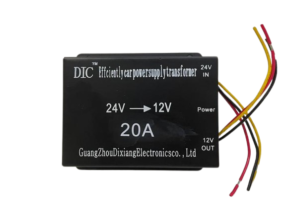
The Step Down 20A DC 24V - 12V Converter is a DC-DC buck converter designed to step down a 24V DC input to a stable 12V DC output. With a maximum current handling capacity of 20A, this converter is ideal for high-power applications. It is commonly used in automotive systems, industrial equipment, and other power supply applications where a reliable 12V output is required from a 24V source.

Explore Projects Built with Step Down 20A DC 24V - 12V Converter DC 20A

Use Cirkit Designer to design, explore, and prototype these projects online. Some projects support real-time simulation. Click "Open Project" to start designing instantly!
Battery-Powered DC-DC Converter System for Multi-Voltage Power Distribution
Image of test 1 ih: A project utilizing Step Down 20A DC 24V - 12V Converter DC 20A in a practical application
This circuit converts a 38.5V battery output to multiple lower voltage levels using a series of DC-DC converters and a power module. It includes an emergency stop switch for safety and distributes power to various components such as a relay module, USB ports, and a bus servo adaptor.
Cirkit Designer LogoOpen Project in Cirkit Designer
Battery-Powered UPS with Step-Down Buck Converter and BMS
Image of Mini ups: A project utilizing Step Down 20A DC 24V - 12V Converter DC 20A in a practical application
This circuit is a power management system that steps down a 240V AC input to a lower DC voltage using a buck converter, which then powers a 40W UPS. The UPS is controlled by a rocker switch and is backed up by a battery management system (BMS) connected to three 3.7V batteries in series, ensuring continuous power supply.
Cirkit Designer LogoOpen Project in Cirkit Designer
USB Power Supply with Overcurrent Protection
Image of USB Charging port: A project utilizing Step Down 20A DC 24V - 12V Converter DC 20A in a practical application
This circuit is designed to step down voltage from a 12V battery to a lower voltage suitable for USB devices. It includes a buck converter connected to the battery through a fuse and fuse holder for overcurrent protection. The output of the buck converter is connected to a USB female port, providing a regulated power supply for USB-powered devices.
Cirkit Designer LogoOpen Project in Cirkit Designer
LED Array with Push Switch Control and Voltage Regulation
Image of Transformer safty device complete: A project utilizing Step Down 20A DC 24V - 12V Converter DC 20A in a practical application
This circuit is a power supply and control system that steps down 220V AC to 24V AC using a transformer, rectifies it to DC using a bridge rectifier, and regulates it to 5V DC. It includes multiple LEDs controlled by push switches and a relay, with a capacitor for smoothing the output.
Cirkit Designer LogoOpen Project in Cirkit Designer

Explore Projects Built with Step Down 20A DC 24V - 12V Converter DC 20A

Use Cirkit Designer to design, explore, and prototype these projects online. Some projects support real-time simulation. Click "Open Project" to start designing instantly!
Image of test 1 ih: A project utilizing Step Down 20A DC 24V - 12V Converter DC 20A in a practical application
Battery-Powered DC-DC Converter System for Multi-Voltage Power Distribution
This circuit converts a 38.5V battery output to multiple lower voltage levels using a series of DC-DC converters and a power module. It includes an emergency stop switch for safety and distributes power to various components such as a relay module, USB ports, and a bus servo adaptor.
Cirkit Designer LogoOpen Project in Cirkit Designer
Image of Mini ups: A project utilizing Step Down 20A DC 24V - 12V Converter DC 20A in a practical application
Battery-Powered UPS with Step-Down Buck Converter and BMS
This circuit is a power management system that steps down a 240V AC input to a lower DC voltage using a buck converter, which then powers a 40W UPS. The UPS is controlled by a rocker switch and is backed up by a battery management system (BMS) connected to three 3.7V batteries in series, ensuring continuous power supply.
Cirkit Designer LogoOpen Project in Cirkit Designer
Image of USB Charging port: A project utilizing Step Down 20A DC 24V - 12V Converter DC 20A in a practical application
USB Power Supply with Overcurrent Protection
This circuit is designed to step down voltage from a 12V battery to a lower voltage suitable for USB devices. It includes a buck converter connected to the battery through a fuse and fuse holder for overcurrent protection. The output of the buck converter is connected to a USB female port, providing a regulated power supply for USB-powered devices.
Cirkit Designer LogoOpen Project in Cirkit Designer
Image of Transformer safty device complete: A project utilizing Step Down 20A DC 24V - 12V Converter DC 20A in a practical application
LED Array with Push Switch Control and Voltage Regulation
This circuit is a power supply and control system that steps down 220V AC to 24V AC using a transformer, rectifies it to DC using a bridge rectifier, and regulates it to 5V DC. It includes multiple LEDs controlled by push switches and a relay, with a capacitor for smoothing the output.
Cirkit Designer LogoOpen Project in Cirkit Designer

Common Applications

  • Automotive systems (e.g., powering 12V devices in 24V trucks or buses)
  • Industrial control systems
  • LED lighting systems
  • Battery-powered devices
  • Communication equipment

Technical Specifications

Below are the key technical details of the Step Down 20A DC 24V - 12V Converter:

Parameter Value
Input Voltage Range 18V - 32V DC
Output Voltage 12V DC (fixed)
Maximum Output Current 20A
Output Power Up to 240W
Efficiency ≥ 95%
Operating Temperature -40°C to +85°C
Protection Features Overcurrent, Overvoltage,
Overtemperature, Short Circuit

Pin Configuration and Descriptions

The converter typically has four connection terminals:

Pin Label Description
1 VIN+ Positive input terminal (connect to 24V source)
2 VIN- Negative input terminal (connect to ground)
3 VOUT+ Positive output terminal (provides 12V output)
4 VOUT- Negative output terminal (connect to ground)

Usage Instructions

How to Use the Converter in a Circuit

  1. Input Connection: Connect the VIN+ terminal to the positive terminal of the 24V DC power source and the VIN- terminal to the ground of the power source.
  2. Output Connection: Connect the VOUT+ terminal to the positive terminal of the load (e.g., a 12V device) and the VOUT- terminal to the ground of the load.
  3. Power On: Ensure all connections are secure, then power on the 24V source. The converter will automatically step down the voltage to 12V.
  4. Load Testing: Verify the output voltage using a multimeter and ensure the load does not exceed the 20A current limit.

Important Considerations

  • Heat Dissipation: At high currents, the converter may generate heat. Ensure adequate ventilation or use a heatsink to prevent overheating.
  • Input Voltage Range: Do not exceed the specified input voltage range (18V - 32V) to avoid damaging the converter.
  • Current Limit: Ensure the connected load does not draw more than 20A to prevent triggering the overcurrent protection.
  • Polarity: Double-check the polarity of the input and output connections to avoid damage.

Example: Using the Converter with an Arduino UNO

The converter can be used to power an Arduino UNO from a 24V source. Below is an example wiring setup:

  1. Connect the VIN+ and VIN- terminals of the converter to the 24V power source.
  2. Connect the VOUT+ terminal to the Arduino's VIN pin and the VOUT- terminal to the Arduino's GND pin.
  3. Ensure the converter is outputting 12V before connecting it to the Arduino.
// Example Arduino code to blink an LED when powered by the converter
// Ensure the converter is providing a stable 12V output to the Arduino UNO

void setup() {
  pinMode(13, OUTPUT); // Set pin 13 as an output for the onboard LED
}

void loop() {
  digitalWrite(13, HIGH); // Turn the LED on
  delay(1000);            // Wait for 1 second
  digitalWrite(13, LOW);  // Turn the LED off
  delay(1000);            // Wait for 1 second
}

Troubleshooting and FAQs

Common Issues and Solutions

  1. No Output Voltage:

    • Check the input voltage to ensure it is within the 18V - 32V range.
    • Verify all connections are secure and polarity is correct.
    • Inspect the converter for signs of damage or overheating.
  2. Output Voltage is Incorrect:

    • Use a multimeter to measure the output voltage. If it is not 12V, the converter may be faulty.
    • Ensure the load is not exceeding the 20A current limit.
  3. Converter Overheating:

    • Check if the load is drawing excessive current.
    • Improve ventilation or add a heatsink to dissipate heat.
  4. Short Circuit Protection Triggered:

    • Disconnect the load and inspect for short circuits.
    • Reset the converter by powering it off and on again.

FAQs

Q: Can this converter be used with a 12V battery as the input?
A: No, the input voltage must be at least 18V. A 12V battery will not provide sufficient input voltage for the converter to function.

Q: Is the output voltage adjustable?
A: No, the output voltage is fixed at 12V.

Q: Can I use this converter to power multiple devices?
A: Yes, as long as the total current draw does not exceed 20A.

Q: Does the converter have reverse polarity protection?
A: No, reverse polarity may damage the converter. Always double-check connections before powering on.