How to Use Audio Jack 4 PIN 3.5mm: Examples, Pinouts, and Specs
Introduction
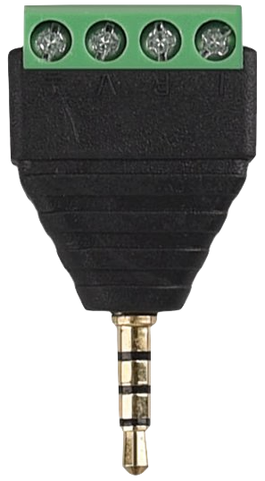
The Audio Jack 4 PIN 3.5mm is a compact and versatile connector commonly used in audio devices. It features four pins that allow for stereo audio output (left and right channels) and a microphone input, making it ideal for headphones, headsets, and other audio peripherals. Its small size and standardized design make it a popular choice for portable devices such as smartphones, laptops, and audio players.
Explore Projects Built with Audio Jack 4 PIN 3.5mm

Explore Projects Built with Audio Jack 4 PIN 3.5mm
Common Applications and Use Cases
- Headphones and headsets with microphone functionality
- Audio input/output for smartphones, tablets, and laptops
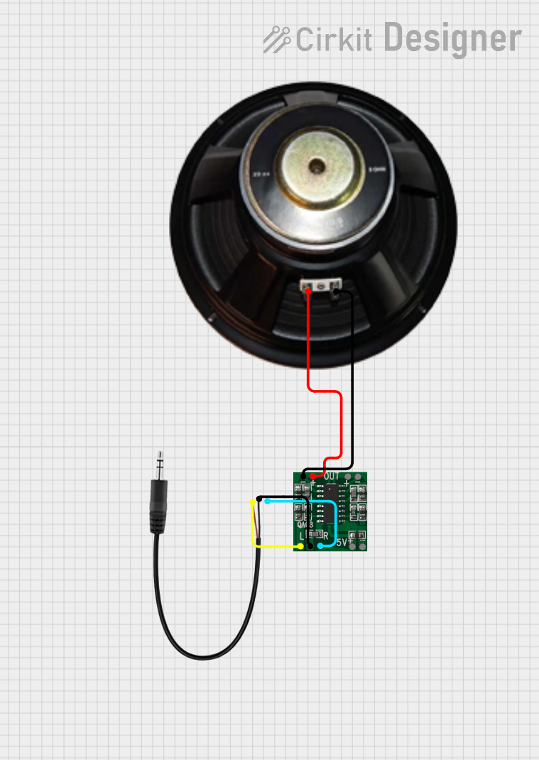
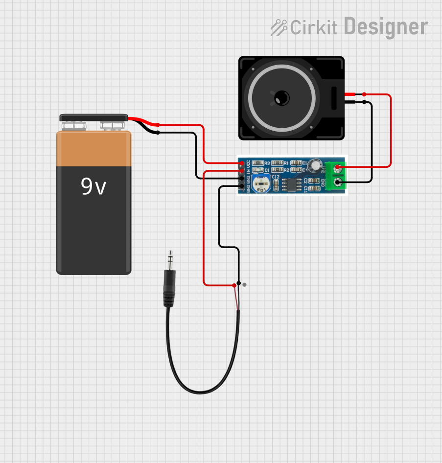
- DIY audio projects and custom audio cables
- Audio recording and playback devices
- Integration into embedded systems for audio communication
Technical Specifications
Key Technical Details
- Connector Type: 3.5mm TRRS (Tip-Ring-Ring-Sleeve) audio jack
- Number of Pins: 4 (Tip, Ring 1, Ring 2, Sleeve)
- Supported Signals: Stereo audio (left and right channels) and microphone input
- Material: Typically gold-plated or nickel-plated contacts for improved conductivity
- Mounting Style: Through-hole or surface-mount, depending on the specific model
- Dimensions: 3.5mm diameter, length varies by model
- Current Rating: Typically up to 1A
- Voltage Rating: Typically up to 12V
Pin Configuration and Descriptions
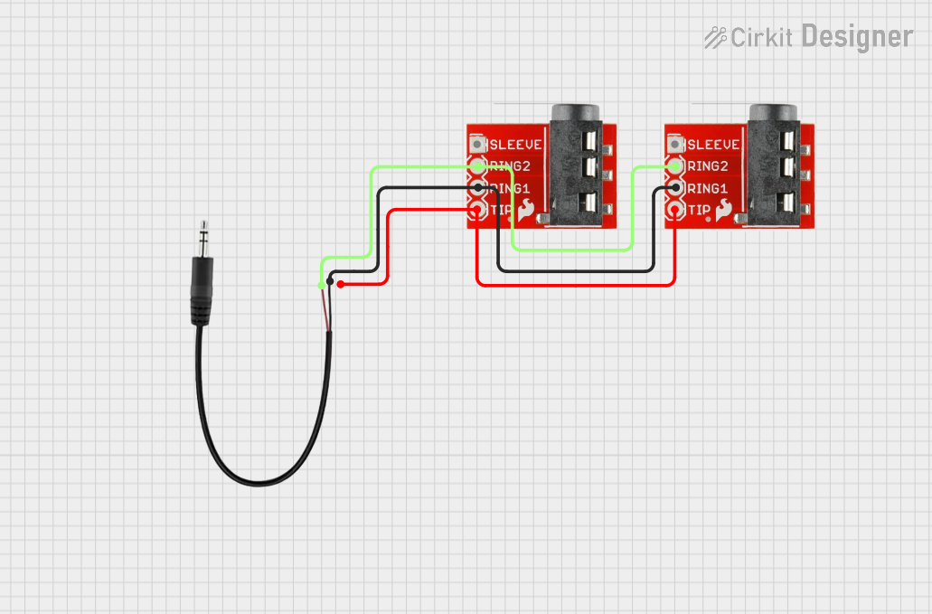
The 4-pin 3.5mm audio jack uses the TRRS (Tip-Ring-Ring-Sleeve) configuration. Below is the pinout description:
| Pin | Name | Description |
|---|---|---|
| Tip | Left Audio | Carries the left audio channel signal. |
| Ring 1 | Right Audio | Carries the right audio channel signal. |
| Ring 2 | Microphone | Carries the microphone input signal. |
| Sleeve | Ground | Common ground for all signals (audio and microphone). |
Note: The pinout may vary slightly depending on the manufacturer or device. Always verify the pin configuration for your specific application.
Usage Instructions
How to Use the Component in a Circuit
- Identify the Pins: Refer to the pin configuration table above to identify the Tip, Ring 1, Ring 2, and Sleeve connections.
- Connect Audio Channels:
- Connect the Tip to the left audio channel output of your circuit.
- Connect Ring 1 to the right audio channel output.
- Connect the Microphone:
- Connect Ring 2 to the microphone input of your circuit.
- Connect Ground:
- Connect the Sleeve to the ground of your circuit.
- Soldering: If using a through-hole version, solder the pins to a PCB. For surface-mount versions, ensure proper alignment and soldering.
- Test the Connections: Use a multimeter to verify continuity and ensure proper connections.
Important Considerations and Best Practices
- Signal Interference: Keep audio signal traces away from high-frequency or high-current traces to minimize noise.
- Connector Durability: Use strain relief or secure the jack mechanically to prevent damage from repeated plugging/unplugging.
- Compatibility: Ensure the pinout matches the device you are connecting to, as some devices may use a different TRRS standard.
- Voltage and Current Limits: Do not exceed the voltage and current ratings of the jack to avoid damage.
Example: Connecting to an Arduino UNO
To use the Audio Jack 4 PIN 3.5mm with an Arduino UNO for audio input or output, you can connect the microphone pin to an analog input pin on the Arduino. Below is an example code snippet for reading microphone input:
// Example: Reading microphone input from a 3.5mm audio jack
const int micPin = A0; // Microphone pin connected to Arduino analog pin A0
int micValue = 0;      // Variable to store the microphone signal value

void setup() {
  Serial.begin(9600); // Initialize serial communication at 9600 baud
}

void loop() {
  micValue = analogRead(micPin); // Read the analog value from the microphone
  Serial.println(micValue);     // Print the microphone value to the Serial Monitor
  delay(100);                   // Delay for 100ms to reduce data output rate
}
Note: Use a capacitor and resistor in the circuit to filter and condition the microphone signal for better results.
Troubleshooting and FAQs
Common Issues and Solutions
No Audio Output:
- Cause: Incorrect pin connections or broken solder joints.
- Solution: Verify the pinout and check all connections with a multimeter.
Static or Noise in Audio:
- Cause: Signal interference or poor grounding.
- Solution: Ensure proper grounding and keep audio traces away from noisy components.
Microphone Not Working:
- Cause: Incorrect connection to the microphone pin or insufficient power to the microphone.
- Solution: Verify the microphone pin connection and ensure the microphone is powered if required.
Loose Connection:
- Cause: Worn-out or damaged jack.
- Solution: Replace the audio jack with a new one.
FAQs
Q: Can I use this jack for mono audio?
A: Yes, you can use the Tip and Sleeve for mono audio. Leave the other pins unconnected.Q: Is this jack compatible with all TRRS devices?
A: Not necessarily. Some devices use different TRRS standards (e.g., CTIA vs. OMTP). Verify compatibility before use.Q: Can I use this jack for digital signals?
A: While primarily designed for analog audio, it can carry low-frequency digital signals if the voltage and current ratings are not exceeded.Q: How do I clean the audio jack?
A: Use a soft brush or compressed air to remove debris. Avoid using liquids unless specified by the manufacturer.
This concludes the documentation for the Audio Jack 4 PIN 3.5mm.