
How to Use IR Sensor Module: Examples, Pinouts, and Specs
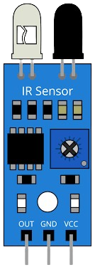
 Design with IR Sensor Module in Cirkit Designer
Introduction
The IR Sensor Module is a versatile electronic component designed to detect infrared radiation. It is commonly used for proximity sensing, object detection, and line-following applications. The module consists of an infrared emitter (IR LED) and a photodetector (such as a photodiode or phototransistor) that work together to detect the presence of objects based on the reflection of infrared light.
Explore Projects Built with IR Sensor Module
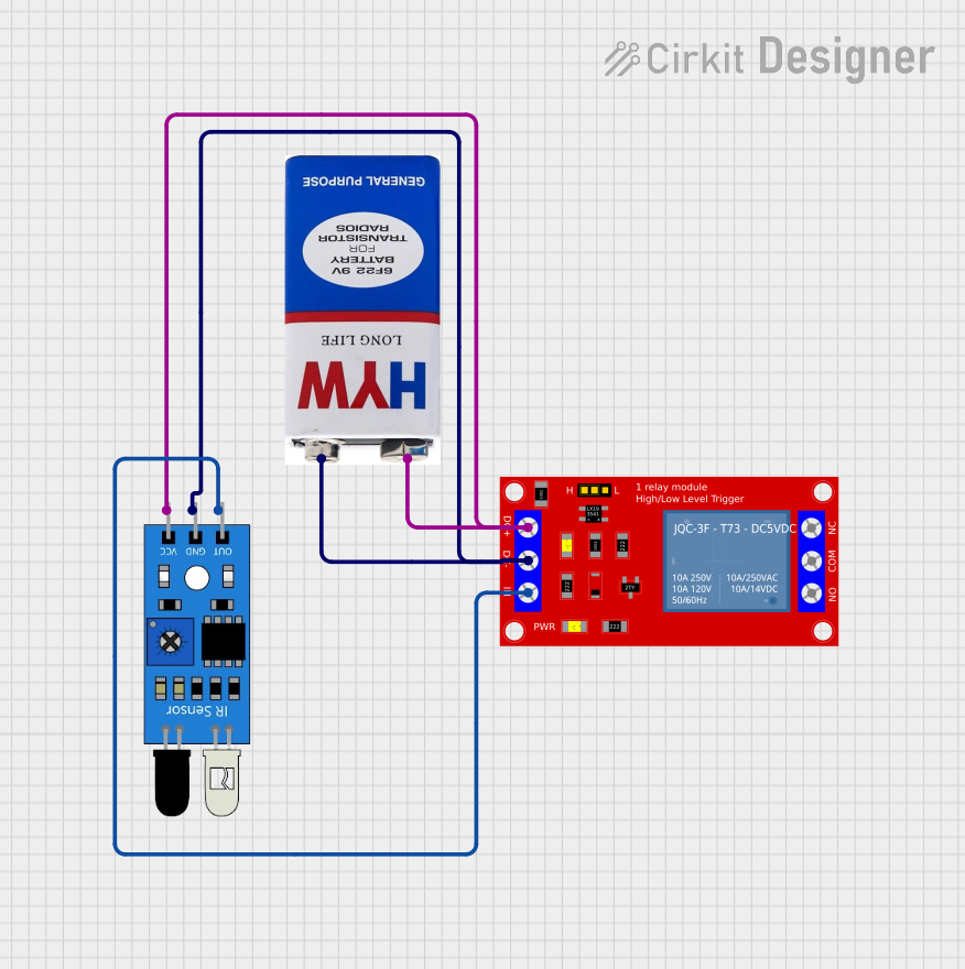 Open Project in Cirkit Designer
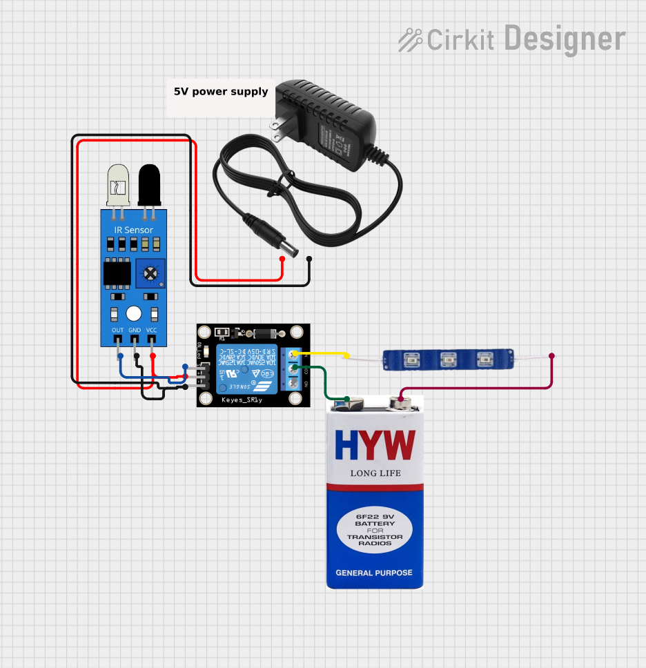 Open Project in Cirkit Designer
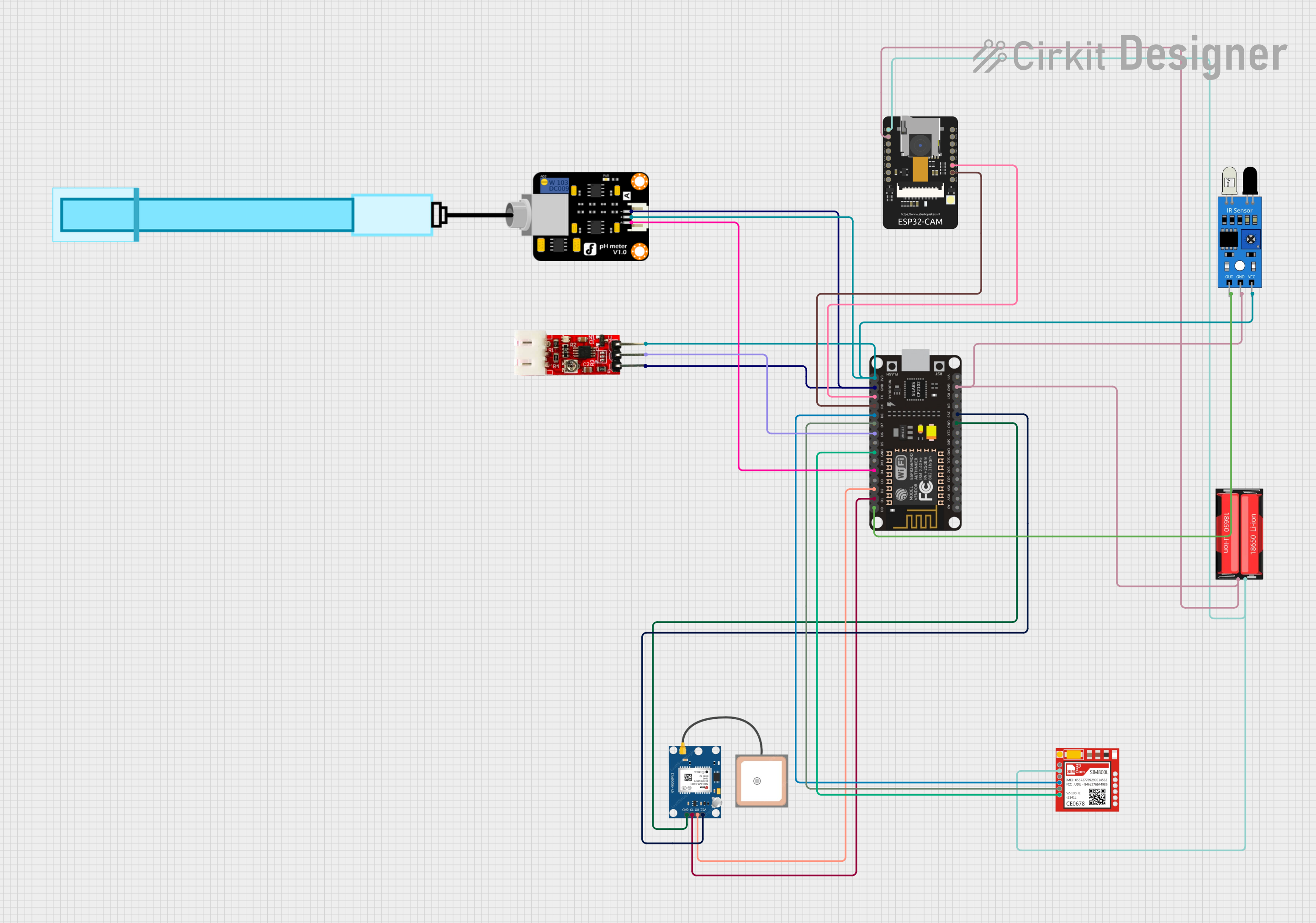 Open Project in Cirkit Designer
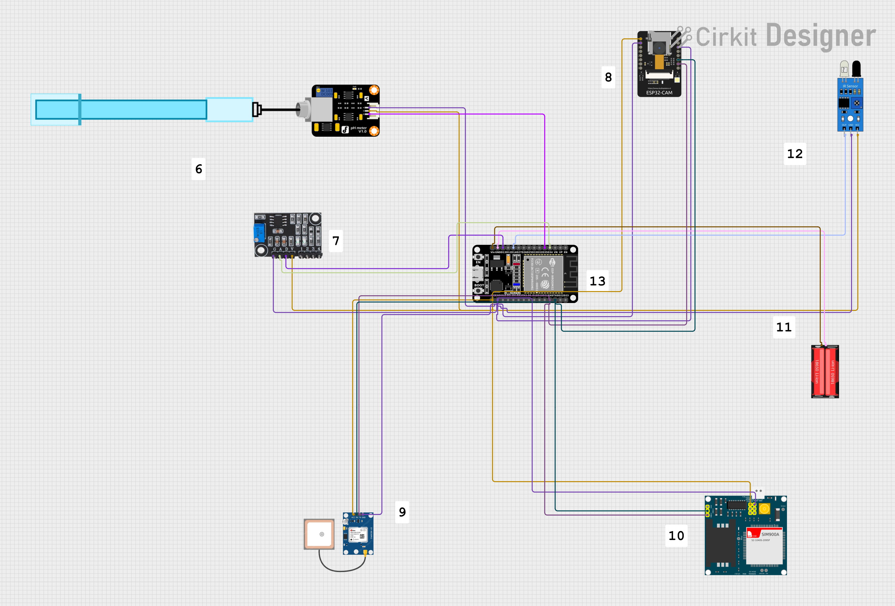 Open Project in Cirkit Designer
Explore Projects Built with IR Sensor Module
Open Project in Cirkit DesignerOpen Project in Cirkit DesignerOpen Project in Cirkit DesignerOpen Project in Cirkit DesignerCommon Applications:
- Obstacle detection in robotics
- Line-following robots
- Automatic door systems
- Hand gesture recognition
- Industrial automation for object counting or sorting
Technical Specifications
Below are the key technical details of a typical IR Sensor Module:
| Parameter | Value |
|---|---|
| Operating Voltage | 3.3V to 5V |
| Operating Current | 20mA (typical) |
| Detection Range | 2cm to 30cm (adjustable) |
| Output Type | Digital (High/Low) or Analog |
| IR Wavelength | 940nm (typical) |
| Dimensions | ~3cm x 1.5cm x 1cm |
Pin Configuration and Descriptions
| Pin | Name | Description |
|---|---|---|
| 1 | VCC | Power supply pin. Connect to 3.3V or 5V. |
| 2 | GND | Ground pin. Connect to the ground of the circuit. |
| 3 | OUT | Output pin. Provides a digital signal (HIGH or LOW) or analog voltage based on the detection. |
Usage Instructions
How to Use the IR Sensor Module in a Circuit
- Power the Module: Connect the
VCCpin to a 3.3V or 5V power source and theGNDpin to the ground. - Connect the Output: Use the
OUTpin to read the sensor's output. This can be connected to a microcontroller (e.g., Arduino) or directly to an LED or buzzer for simple applications. - Adjust the Sensitivity: Most IR Sensor Modules include a potentiometer to adjust the detection range. Turn the potentiometer clockwise or counterclockwise to increase or decrease sensitivity.
Important Considerations and Best Practices
- Ambient Light Interference: IR sensors can be affected by strong ambient light. Use the module in controlled lighting conditions for optimal performance.
- Reflective Surfaces: The module works best with reflective surfaces. Matte or dark surfaces may reduce detection accuracy.
- Power Supply: Ensure a stable power supply to avoid erratic behavior.
- Testing the Output: Use an LED or multimeter to verify the output signal before connecting it to a microcontroller.
Example: Connecting to an Arduino UNO
Below is an example of how to connect and use the IR Sensor Module with an Arduino UNO:
Circuit Connections:
VCC→ 5V on ArduinoGND→ GND on ArduinoOUT→ Digital Pin 2 on Arduino
Arduino Code:
// IR Sensor Module Example with Arduino UNO
// This code reads the digital output of the IR sensor and turns on an LED
// when an object is detected.

const int irSensorPin = 2;  // IR sensor output pin connected to digital pin 2
const int ledPin = 13;      // Onboard LED pin

void setup() {
  pinMode(irSensorPin, INPUT);  // Set IR sensor pin as input
  pinMode(ledPin, OUTPUT);      // Set LED pin as output
  Serial.begin(9600);           // Initialize serial communication for debugging
}

void loop() {
  int sensorValue = digitalRead(irSensorPin);  // Read the IR sensor output

  if (sensorValue == LOW) {
    // Object detected (LOW signal indicates detection)
    digitalWrite(ledPin, HIGH);  // Turn on the LED
    Serial.println("Object detected!");
  } else {
    // No object detected
    digitalWrite(ledPin, LOW);   // Turn off the LED
    Serial.println("No object detected.");
  }

  delay(100);  // Small delay for stability
}
Troubleshooting and FAQs
Common Issues and Solutions
The sensor is not detecting objects:
- Ensure the
VCCandGNDconnections are correct. - Adjust the potentiometer to increase the sensitivity.
- Check for obstructions on the IR LED or photodetector.
- Ensure the
False detections in bright environments:
- Avoid using the sensor in direct sunlight or near strong light sources.
- Use an IR filter or shield the sensor from ambient light.
Output signal is unstable:
- Verify that the power supply is stable and within the specified voltage range.
- Check for loose connections or damaged wires.
The detection range is too short:
- Adjust the potentiometer to increase the range.
- Ensure the object being detected has a reflective surface.
FAQs
Q: Can the IR Sensor Module detect transparent objects?
A: Transparent objects, such as glass, may not reflect enough infrared light for detection. Use specialized sensors for such applications.
Q: How do I know if the sensor is working?
A: Most IR Sensor Modules have an onboard LED that lights up when an object is detected. You can also verify the output using a multimeter or microcontroller.
Q: Can I use the IR Sensor Module with a 3.3V microcontroller?
A: Yes, the module is compatible with both 3.3V and 5V systems. Ensure the VCC pin is connected to the appropriate voltage.
Q: What is the maximum detection range of the module?
A: The detection range is typically adjustable between 2cm and 30cm, depending on the module and environmental conditions.